


Abstract
Aims High voltage electric current can adversely affect pacemakers (PM) and implantable cardioverter-defibrillator (ICD). The standard shock from an electrical stun gun (TASER- X26®, TASER International, Scottsdale, AZ) consists of a 5-s long application of high voltage, low current pulses at 19 pulses per second. Its effect on the functional integrity of PM and ICDs is unknown.
Methods and results We tested the functional integrity of nine PMs and seven ICDs in a swine model after a standard stun gun shock. A transvenous, dual coil, bi-polar ICD lead (St Jude-SP01) and a PM lead were placed in the right ventricular (RV) apex and connected to pulse generators buried in the pre-pectoral pocket. The two darts were placed at the sternal notch (SN) and apex of the heart bracketing the device pocket. Standard neuromuscular incapacitating (NMI) discharges were delivered. Functional parameters of the devices and leads were checked before and after the shocks. The mean pacing thresholds, sensing thresholds, pacing impedances, and defibrillation coil impedances of the ICD lead were similar before and after the shocks. Similarly, pacing thresholds, sensing thresholds, and impedances of the PM lead were not significantly different before and after the shocks. No significant change was noted in battery voltage and projected longevity. Implantable cardioverter-defibrillator generators detected the NMI impulses at a mean cycle length of 176 ± 20 ms with detection to charge time of 5.9 ± 1.5 s. Shock delivery was aborted in all tests as tachycardia detection abruptly terminated at the end of the 5 s NMI application. None of the devices exhibited power on reset (POR), elective replacement indicator (ERI), or noise mode behaviour after the shock.
Conclusion Pacemakers and ICD generators and leads functions were not affected by the tested standard 5 s stun gun shocks.
Introduction
The use of neuromuscular incapacitation devices (NMIDs) is gaining popularity over traditional lethal and non-lethal weapons by law enforcement personnel internationally.1 These devices typically deliver rapid pulses of high-voltage short pulse widths that generate involuntary neuromuscular stimulation with incapacitation. A commonly used NMID is the TASER-X26. Such stun devices are used by more than 7000 law enforcement departments across the United States and have been used more than 200 000 times.2 Recent reports have raised concern over a possible association between NMIDs and more than 100 deaths.3 However, many factors can contribute to in-custody deaths of an arrested person. Thus, a direct cause and effect relationship between TASER use and death typically cannot be determined even with forensic analyses.4,5 The data on the cardiovascular safety of these devices is conflicting. A recent study by Mc.Daniels et al. and our group had indicated a high safety margin for ventricular fibrillation (VF) induction by NMIDs.6,7 Another study by Nanthakumar et al. had shown that close to the heart there is a higher rate of myocardial capture and induced VF on a rare occasion with epinephrine.8 A recent study involving healthy human volunteers has demonstrated general cardiac safety of a TASER X-26 application and no significant effects on the electrocardiogram.9
A potential interaction between NMIDs and implantable cardiac devices, such as permanent pacemakers (PMs) and implantable cardioverter-defibrillators (ICDs), has not been studied previously in a systematic fashion. Implantable cardiac devices are susceptible to malfunction as a result of electromagnetic interference (EMI). Electromagnetic interference can result in many undesirable consequences, including damage to internal circuitry, oversensing, undersensing, failure to pace, failure to capture, power on reset (POR), triggering of elective replacement indicators (ERI), and inappropriate defibrillation therapy.8–18 This study evaluates the immediate effects of NMID discharges on the function of implanted cardiac PMs and ICDs.
Methods
Electrical stun device
The TASER® X26 is a 26-W pistol-like device that shoots two tethered darts and delivers up to 6000 V (typical output about 1500 V) of peak electrical potential in rapid pulses (19 pulses per second) over 5 s. This is the most popular stun gun model sold in the market. It also delivers an open circuit voltage of up to 50 000 V to arc through clothing in case a direct connection is not made. This arcing voltage is strictly ‘open-circuit’ and is never seen across the body and is thus not relevant to stimulation. Once current starts to flow across the arc, impedance drops immediately and the voltage of delivered current also drops to levels below 6000 V.
Briefly, the pulse waveform, as previously reported6 has an initial rapid downward ‘arcing phase’ and then an upward slope followed by a delayed decaying waveform with pulse duration of about 100 µs and a net delivered charge of about 100 µC (Figure 1). The peak current during the pulse is in the 2 to 3 A range. While the average current during the pulse is near 1 A. The average net current is <2 mA [I = Q/t = 100 µC/(1/19 s) = 1.9 mA, i.e <2 mA]. The energy per pulse is about 70 mJ so the average output power is <1.5 W [P = W/t = 70 mJ/(1/19 s) = 1.33 W, i.e <1.5 W]. The tethers are insulated wires that carry the charge from the gun to the darts.
The pulse waveform of TASER X-26 current.
Experimental protocol
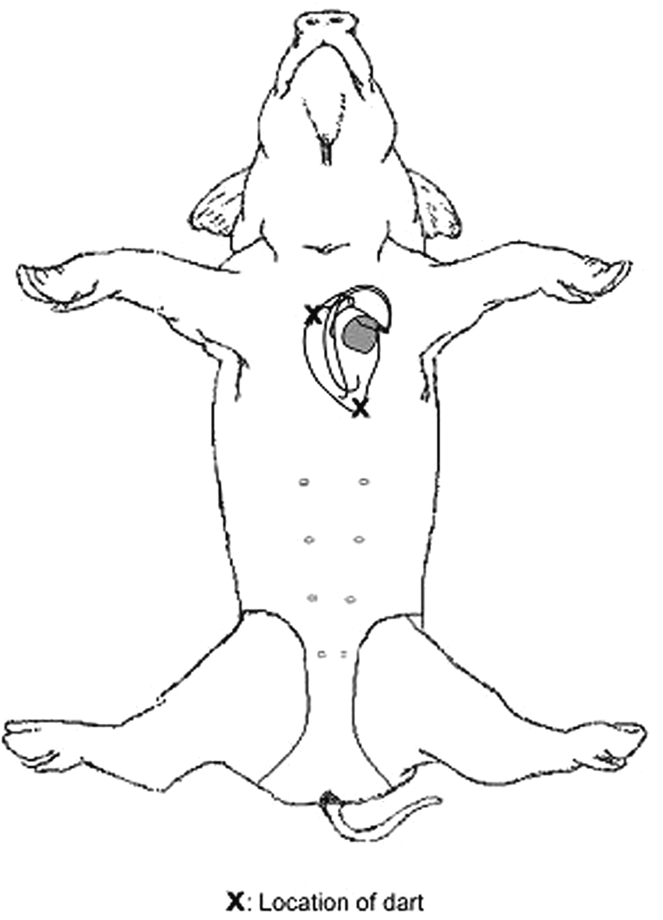
The animal research committee at our institution approved this study. A small adult male pig (28 kg) was sedated with 12 mg/kg of intramuscular ketamine and then intubated. Anaesthesia was maintained with 1 to 2% isoflurane mixed with oxygen and nitrous oxide. The SN and the point of maximum palpable impulse (PMI) were marked on the ventral surface of the pig. Two tethered darts (0.89 cm deep) were inserted to full depth at the SN and PMI. The PMI dart was ∼1.5 cm from the epicardial surface as measured by echocardiography. These two points were chosen as they were demonstrated in other experiments from our laboratory to be the sites where NMI stimulation most likely captured the myocardium. In addition, these two sites readily bracketed the anterior chest wall device pocket. Transcutaneous patches were placed to defibrillate the pig externally if needed. A prepectoral subcutaneous pocket that lies in between the darts was created to house the generator. A 70 cm long, transvenous, bipolar, dual-coil, St Jude SPLTM cardioverter defibrillator lead (Model No. SP-01, St Jude Medical, St Paul, MN) and a 52 cm long St Jude Isoflex (Model No. 1648T, Jude Medical, St Paul, MN) transvenous, bipolar, passive-fixation, pace-sense lead were placed in the right ventricle through the left internal jugular vein. Both leads were tunnelled from the neck into the pre-pectoral pocket and were connected to a pacemaker or ICD generator specified in Tables 1 and 2. Figure 2 shows a fluoroscopic view of the device and leads in the pig's body. The generator pocket was positioned in between the two points of dart insertions (Figure 3). The pace-sense leads were programmed bipolar. The tethered darts were attached to a plastic cartridge and loaded to the front of the stun gun. Discharges were delivered through the darts to the above-mentioned sites. All the devices were tested in a single animal and each of the devices was tested with three standard NMI discharges of 5 s duration each. In addition, a 5 s long NMI discharge was applied on the dorsum of the pig with the ICDs implanted to assess for device detection of the electrical impulses. All devices were programmed to VVI mode at 60 bpm with the sensing programmed to 2 mV for pacemakers and 0.3 mV maximal sensitivities for ICDs, values in a range typical for clinical programming. For ICDs, tachyarrhythmia detection was programmed to 180 bpm with up to four shocks at maximum energy. Each PM or ICD generator was connected to the appropriate lead and buried in the pre-pectoral pocket before NMI discharge. Before and after each discharge, lead and generator functions were assessed with a device interrogator specific to the manufacturer. Pacing and sensing thresholds as well as pacing and shocking coil impedances were determined before and after each of the three NMI discharges. The average of the three post-discharge value was considered for analysis. Defibrillation threshold testing (DFT) was not done. The generators were monitored for abnormal behaviour, including oversensing, undersensing, failure to pace, failure to capture, POR, ERI, and inappropriate defibrillation therapy. At termination of the experiment, the pig was euthanized with VF induction using a 9 V DC battery.
Fluoroscopic image of the generator and the leads in place in the pig model.
Line diagram representing the location of the heart and the relative position of the darts through which the NMI current is applied.
Pre- and post-shock evaluations of ICD systems
| Manufacturer | Model | Bat V pre-shock | Bat V post-shock | R pre-shock | R post-shock | PT pre-shock | PT post-shock | LI pre-shock | LI post-shock | DFCI pre-shock | DFCI post-shock | DCL | CT |
|---|---|---|---|---|---|---|---|---|---|---|---|---|---|
| Guidant | Vitality DS | 3.20 | 3.20 | 9.3 | 7.1 | 1.4–0.5 | 0.4–0.5 | 394 | 369 | 54 | 52 | 178 | 7.6 |
| Guidant | Ventak MS | 2.58 | 2.58 | 8.0 | 7.8 | 0.2–0.5 | 0.2–0.5 | 389 | 397 | 50 | 49 | 160 | 5.4 |
| Guidant | Vitality DS | 3.19 | 3.19 | 8.0 | 6.9 | 0.2–0.5 | 0.2–0.5 | 352 | 354 | 50 | 52 | 154 | 4.9 |
| Guidant | Ventak DR | 2.93 | 2.93 | 8.0 | 7.0 | 0.2–0.5 | 0.2–0.5 | 367 | 348 | 54 | 51 | 169 | 8.4 |
| Medtronic | 7273 | 5.16 | 5.16 | 7.5 | 7.5 | 2.0–0.4 | 2.0–0.4 | 500 | 474 | 59 | 59 | 210 | 5.6 |
| St Jude | Atlas DR | 3.10 | 3.10 | 4.2 | 4.9 | 0.2–0.5 | 2.2–0.5 | 395 | 380 | 44 | 44 | 196 | 5.2 |
| St Jude | Photon VR | 3.00 | 3.00 | 4.3 | 4.4 | 0.2–0.5 | 1.0–0.5 | 355 | 375 | 46 | 46 | 165 | 4.3 |
| Mean | 3.31 | 3.31 | 7.0 | 6.5 | 0.6 | 0.9 | 393 | 385 | 51 | 50 | 176 | 5.9 | |
| SD | 0.84 | 0.84 | 2.0 | 1.3 | 0.8 | 0.9 | 50 | 42 | 5 | 5 | 20 | 1.5 |
Bat V, battery voltage in V, R, R waves sensing threshold in mV, PT, pacing threshold in volts milliseconds, LI, lead impedance in Ohms, DFCI, defibrillation coil impedance, DCL, detected cycle length in milliseconds, CT, charge time in seconds.
Data analysis
Variables are reported as means with SDs. The Wilcoxon signed ranks non-parametric test was used to compare pre- and post-values across the models tested.
Results
We studied the effects of NMI (TASER-X26) on seven ICDs and nine PMs. The measured parameters determined before and after the NMI application are shown in Table 1 for defibrillators and Table 2 for pacemakers. As the tables show, there was no statistically significant change of these parameters. Small differences in individual measurements can be attributed to variations from repeated measures or small shifts of the lead after applying NMI.
Pre- and post-shock evaluation of pacemaker systems
| Manufacturer | Model | Bat V pre-shock | Bat V post-shock | R pre-shock | R post-shock | PT pre-shock | PT post-shock | LI pre-shock | LI post-shock |
|---|---|---|---|---|---|---|---|---|---|
| Medtronic | Insync | 2.95 | 2.95 | 8.0 | 8.0 | 0.5–0.5 | 0.5–0.5 | 422 | 409 |
| St Jude | Enpulse | 2.75 | 2.75 | 5.6 | 5.6 | 0.25–0.52 | 0.75–0.52 | 417 | 423 |
| St Jude | Identity DR | 2.73 | 2.71 | 5.0 | 5.3 | 0.25–0.5 | 0.25–0.5 | 334 | 356 |
| St Jude | Affinity DR | 2.75 | 2.75 | 7.0 | 7.0 | 0.25–0.8 | 0.25–0.8 | 374 | 374 |
| St Jude | Integrity AF | 2.75 | 2.76 | 6.2 | 6.4 | 0.25–0.4 | 0.25–0.4 | 401 | 383 |
| St Jude | Affinity DR | 2.76 | 2.76 | 7.0 | 7.0 | 0.25–0.5 | 0.25–0.5 | 373 | 403 |
| Medtronic | Insync | 2.77 | 2.77 | 8.0 | 8.0 | 0.5–0.5 | 0.5–0.5 | 426 | 422 |
| Guidant | Meridian | 2.78 | 2.76 | 5.7 | 5.3 | 0.3–0.5 | 0.3–0.5 | 410 | 400 |
| Guidant | Pulsar max | 2.86 | 2.85 | 5.1 | 5.8 | 0.2–0.4 | 0.3–0.4 | 380 | 380 |
| Mean | 2.79 | 2.78 | 6.40 | 6.48 | 0.3 | 0.4 | 393.00 | 394.44 | |
| SD | 0.07 | 0.07 | 1.15 | 1.07 | 0.1 | 0.2 | 30.15 | 22.71 |
Bat V, battery voltage in V, R, R waves sensing threshold in mV, PT, pacing threshold in volts milliseconds, LI, lead impedance in Ohms, DFCI, defibrillation coil impedance, DCL, detected cycle length in milliseconds, CT, charge time in seconds.
As might be expected, significant electrical artifact was seen on telemetry monitoring of the device electrogram during the entire 5 s long NMI discharge. Thus, real-time monitoring of the electrogram was not possible. Tachycardia detection by all the ICDs occurred during standard NMI discharge and caused the devices to start charging. Interrogation of the devices after the NMI applications showed the recorded electrograms during the NMI application. An example is shown in Figure 3. The mean detected CL during NMI application was 176 ± 20 ms, with an average detection to charge time of 5.9 ± 1.5 s. The VF sensing refractory period for ICDs tested ranged from 120 to 135 ms depending on the manufacturer. The cycle lengths of the ICD detections corresponded best to the rates of stimulus artefact seen on the sensing ventricular electrograms interrogated from ICD memory, taking into account the sensing refractory periods of 120–135 ms that is inherent to most of the ICDs. Variable ventricular capture rates can be seen during application of the NMI (see Figure 4) and did not correspond to the detection rates of the ICD. However, no VF or VT was induced at the end of the standard application. The rapid NMI pulses initiated the detection sequence followed by capacitor charging. Tachycardia detection abruptly terminated with completion of the 5 s NMI discharge and shock delivery was aborted as all of these devices were programmed to non-committed first shocks. Figure 3 illustrates one example of such detection, charge, and aborted therapy sequence. In our tested devices, the minimum charge time to shock delivery was >5 s and the standard NMI discharge did not last long enough to complete the detection sequence for delivering a shock. None of the devices exhibited POR, ERI, or noise mode behaviour after the NMI discharges.
ICD memory record of NMI discharge. This interrogated electrogram strip from the ICD memory after the NMI application shows onset of rapid rate detection with initiation of the application. The device responds by starting to charge its capacitors. However, prior to shock delivery, the application is terminated and the device aborts the shock delivery. Note that detected cycle length corresponds best to the detected NMI pulses rather than the ventricular electrograms even though accelerated ventricular capture can be appreciated visually at cycle lengths around 240 ms.
Discussion
The cardiac effects of NMIDs (TASER®) have been a subject of debate for several years with some uneasy questioning about their absolute safety. A recent study using a porcine model suggested that NMI devices do not cause cardiac arrhythmias within limits of the standard electrical discharge.6 Multiple applications of the NMI discharge were reported safe as well.6 Similarly, NMIDs were not found to cause arrhythmias when applied to healthy human volunteers.7 In the current study, we attempted to answer an important question as to what happens when a NMID is applied near a pacemaker or ICD. Although field experience suggests that the paired application would mostly not be close to a typical pectoral pacemaker site, we tested these devices with the darts placed closely on either side of it on the chest wall to simulate the common positioning of such devices in humans.
Our observations indicate that the implanted device would likely detect NMI discharges impulses applied along the axis of the heart. The detected pulse amplitudes are significantly larger than that of the ventricular electrogram. Thus, for pacemakers and ICDs this detection would likely inhibit pacing output. In ICDs this detection would also initiate charging of the capacitors in preparation for shock delivery. While all the ICDs we tested initiated capacitor charging during the NMI application, shock delivery was aborted as tachyarrhythmia detection stopped at the end of the 5 s long application (Figure 3). The average ICD charge time was 6.2 s. Haegli et al. in a recent report of an ICD patient receiving a TASER shock observed findings similar to our study.19 Interrogation of the device in that patient indicated capacitor charging in response to detection of the rapid TASER pulses but the shock was aborted due to termination of the pulses prior to shock delivery. We did not program the device to a low-energy shock, where the charge time may have been quite short and completed within the applications time of the NMI pulses. Under those circumstances, where the detection and charge times can be under 5 s, it is conceivable that a shock could be delivered prior to the termination of the 5 s NMI application.
Our results indicate that there was no change in the integrity of pacing and sensing functions of both the ICD and the PM leads. There was no immediate damage to implanted pacemakers and defibrillators generators caused by the standard NMI discharge. A 5 s NMI discharge did not seem to be detrimental to pacemaker or ICD lead function and integrity acutely. Our experimental design, of course, could not exclude the potential that repeated applications of these shocks may cause cumulative damage to the generators or that single applications may lead to long-term malfunction of these devices.
External or internal-defibrillation is known to sometimes result in reset mode, ERI, or transient elevation of capture and sensing thresholds mostly in older unipolar systems.15–18 The 360 J of an external defibrillator is rather large compared with the 70 mJ of an X-26 pulse. The total energy delivered in 5 s of standard NMI discharge is about 7 J. The amount of energy generated during a standard NMI discharge is significantly lower than that of external defibrillation. At 19 pps, the total energy delivered per second is only 1.33 J. Due to the rapid cooling effects of the blood, cumulative energy delivered over longer time periods may not achieve clinical significance. The differences in the waveform and short duration of application along with the built in protective mechanisms of the newer generation pulse generators most likely explain the findings of our study. Non-conducting circuit shields, small inter-electrode distance that minimizes the antenna effect, and incoming signal filtering usually protect the devices from EMI. Noise protection algorithms in the timing cycles act as a second level of protection in decreasing the EMI effects.8 There is less propensity for sensing of external electrical fields and electrocautery with bipolar sensing systems.10,17,20 However, the NMI impulses generate such a large signal when applied close to the generator (Figure 3) that sensing of the impulses is likely. In the ICDs we tested. All devices sensed the NMI impulses. The results of our study would indicate that even where the device generator is sandwiched in between the applied darts, NMI applications are unlikely to damage or cause malfunction of pacemakers or ICDs, at least in the short-term. Temporary inhibition of pacing is likely during the NMI application. For prolonged application over 5 s, an ICD may discharge a shock that is programmed in the defibrillation zone. Repeated delivery of the standard 5 s TASER application separated by short durations may also result in an ICD discharge if the second application occurs at the time of tachycardia confirmation.
Study limitations and implications
The findings of this study are limited to TASER-X26 model only and may not be generalized to other models of stun guns available in the market. A single animal was used to test all the devices and this may limit the assessment of the effect of biological variations on the reproducibility of our findings. However, the animal used in this study served as a biological ‘platform’ for the testing. It is unlikely that such variation among animals is of sufficient magnitude to justify the use of multiple animals to assess this potential biologic variability. This study tested two acutely implanted RV lead models. We did not assess the effect of NMI discharge on atrial leads. While the electrical characteristics of most modern pacemaker and ICD leads are similar, extrapolation of our results to other lead models should be done with caution. A limited number of devices from only a few manufacturers were tested in this study. The long-term effects on pacing and sensing thresholds and generator function were not assessed. Our experiments only evaluated the standard 5 s delivery of the TASER X26 pulses. Longer deliveries are possible with his weapon. Prolonged continuous application is discouraged by the manufacturer's training guidelines. However, there is the possibility of that a law enforcement officer may use a longer application when faced with a tough subject on whom a standard application was ineffective. Lastly, we only evaluated the bipolar setting for pacemakers. Thus, we did not test whether circuitry protection within the pacemaker generators would have behaved differently had a unipolar configuration been used.
Conclusion
NMI discharge does not affect the short-term functional integrity of implantable pacemakers and defibrillators even when the darts are placed in a manner to sandwich the generator. The standard NMI application duration of 5 s should not trigger an ICD shock in devices programmed to a non-committed shock delivery mode.
Acknowledgements
We thank Subramanya Prasad MD and Bruce Wilkoff MD for their valuable feedback in the preparation of this manuscript. This study was funded by a modest unrestricted educational grant from TASER International, Scottsdale, AZ. The funding source had no input on the study design, organization, results, and manuscript preparation. None of the contributing authors have any kind of financial or any other conflict of interest with the funding source.
