
Abstract
High-intensity focused ultrasound (HIFU) is one of the noninvasive treatment for tumors. Visualizing the treated area inside the human body is necessary to control the HIFU exposure. Localized motion imaging (LMI) using ultrasound to induce and detect tissue deformation is one technique to detect a change in tissue stiffness caused by thermal coagulation. In experiments with porcine liver, LMI has shown to detect deformation with less than 20% accuracy. We have developed a prototype feedback control system using real-time LMI. In this system, coagulation size was measured every 1 s and controlled to correspond to a targeted size. The typical size error was reduced to 14% from 35%. LMI displacements in normal and coagulated tissues were sufficiently different to discriminate between coagulated areas and noncoagulated ones after HIFU sonication and to visualize treated areas after HIFU treatment.
Export citation and abstract BibTeX RIS
1. Introduction
Recently, high-intensity focused ultrasound (HIFU) has been proposed as one of the minimally invasive treatment modalities for cancerous tumors.1–5) A high-energy acoustic beam can produce irreversible thermal coagulation and tissue necrosis at its focal point. The high-energy region can be confined to the focal region without inducing irreversible thermal damage to the surrounding normal tissue. This modality enables a reduced hospital stay and repeatable treatment for cancer after reoccurrence or incomplete treatment. However, living tissues are acoustically and thermally inhomogeneous; therefore, it is necessary to develop an accurate monitoring system to control the thermal dose.
Magnetic resonance imaging (MRI) is currently used as the standard noninvasive guidance and monitoring modality for HIFU, because it can provide quantitative spatial maps of induced temperature increases.6,7) However, MRI-guided treatment is expensive, and temporal resolution is not sufficient for HIFU treatment as a feedback control. Therefore, ultrasound (US) imaging has been studied as a monitoring modality for noninvasive HIFU treatment.8) The advantages of US imaging are portability of the unit, low cost, and spatiotemporal resolution. However, the longitudinal wave speed which is one of the acoustic properties changes only a few percent before and after thermal coagulation.9–11) It is difficult to detect the coagulation region in a B-mode image.8,12,13) The boiling area was successfully visualized in a real-time US echo image; however, this visualized area is smaller than the actual coagulated area.8) Temperature change estimation based on sound speed change has been attempted, but precise echo-based temperature estimation has been difficult.12) The temperature dependence of sound speed is highly dependent on the local ratio of fat to water, and this ratio is unknown in many cases. Evaluating loss correlation in echo signals before and after coagulation was one promising approach.13) This method is good for monitoring during treatment; however, if the object moves during or after treatment and information about orientations lost, echo correlation cannot be applied. In contrast, stiffness is a mechanical property of living tissue which changes dramatically, and these changes remain after treatment. In a typical experiment with liver tissue, the shear modulus after coagulation was approximately 10 times higher than that before coagulation.11)
Elastography is being developed as a monitoring method based on US to display tissue stiffness distribution in the human body.14) In this method, a tissue elasticity map is created from tissue deformation distribution due to a stress induced from the surface of the body. Magnetic resonance elastography (MRE) is elastography combined with MRI and an external vibrator to induce shear waves.15) Recently, elastography using acoustic radiation force has been studied. Acoustic radiation force imaging (ARFI) can provide a quantitative stiffness map by pushing a tissue with localized radiation force deep in the human body.16,17) Supersonic shear imaging (SSI)15,18) and shear wave elastography imaging (SWEI)19,20) use shear waves propagated in the human body to create a stiffness distribution map.
To detect localized stiffness changes, several groups have studied harmonic motion imaging (HMI).20–22) In this method, amplitude modulated acoustic radiation force is used as a mechanical input to deform tissues at the focus, and the tissue deformation observed is on the order of tens of µm. Tissue stiffness increases after coagulation. The magnitude of the tissue deformation reflect the average elastic modulus in a local oscillating region. After coagulation, the tissue deformation is smaller than before coagulation; therefore, this method uses the ratio of deformation between before and after coagulation to estimate the size of the coagulated area. HMI techniques have been applied as monitoring methods for feedback systems through the detection of the onset of coagulation to achieve secure HIFU ablation23) and two-dimensional (2D) mapping.24)
Localized motion imaging (LMI) is an HMI-based method for improving the detection sensitivity for small coagulated areas.25) In this study, the objective is the development of HIFU to control coagulation size on the basis of real-time LMI. The estimation of coagulation size to control HIFU ablation should be realized within 1 s. The targeted error level is less than 10% to detect a coagulation length of 10 mm.
2. Experimental methods
2.1. LMI
LMI is one of the techniques of detecting a change in tissue stiffness caused by thermal coagulation in HIFU treatment. In this method, acoustic radiation force described in Eq. (1)26) generated by HIFU is used as a mechanical input to deform tissue at the focus; the magnitude of tissue deformation is tens of µm.
The term, α is an absorption coefficient, I is the US intensity, and c is the speed of sound. The acoustic radiation force is modulated by changing the amplitude of the US intensity. The size of the local oscillated area can be controlled by amplitude modulation (AM) frequency. Using a high AM frequency, the size of the oscillated area can be localized owing to short effective propagation length caused by increased attenuation of shear waves. Therefore, AM frequency is an important parameter for controlling the detection sensitivity of the coagulated area through changes in the average stiffness. Tissue deformation is measured using a pulse–echo method with an imaging probe placed at the center of the HIFU transducer. After coagulation, tissue stiffness changes are detected as changes in tissue deformation. The coagulated area is estimated from the decrease in the ratio of tissue deformation before to after coagulation. A flow chart of the signal processing method for 1D LMI is shown in Fig. 1. In the fourth step of this process, a Hanning type band-pass filter from 2 to 8 MHz was applied to obtain RF data to eliminate signal at 2 MHz relating to HIFU beam or noises in the higher frequency domain. In the seventh step of this process, the following error elimination process was applied to an estimated displacement map. If a cross-correlation value was less than 0.8, the estimated displacement was replaced by a value interpolated from estimated values in neighboring pixels.

Fig. 1. Data processing sequence of LMI.
Download figure:
Standard image High-resolution image2.2. Experimental setup
A custom-made, single-element concave HIFU transducer (Fuji Ceramics PZT4, C213) operating at a central frequency of 2.2 MHz was used to induce both localized motion and thermal coagulation in the tissue. This transducer was 100 mm in diameter with a central hole of 40 mm diameter and a focal length of 100 mm. The full width at half maximum (FWHM) of intensity along a beam axis of the transducer was approximately 8 mm. A custom-made 128-element linear array diagnostic transducer (Hitachi Aloka Medical) was placed at the center of the HIFU transducer so that the direction of the beam axis of the linear array transducer coincided with that of the HIFU transducer. The diagnostic transducer had a central frequency of 5 MHz, and it was connected to a modified US imaging system (Hitachi Aloka Medical F75 modified). To verify alignment and ensure that the US diagnostic transducer was effectively observing the HIFU focal point, the assembly was placed in a water tank and both beam axes were measured using a needle hydrophone (Imotec 80-0.5-4.0, 0.5 mm diameter). The water was degassed by a degasifier (ERC 3302W), and filtered by an activated carbon filter and membrane filter (ORGANO PF-CB) with a pump (KNF LIQUIPORT® NF100KT18S).
The transducer assembly was mounted on an arm and introduced into a water tank facing the target liver tissue, which was embedded in polyacrylamide gel. The acoustic properties such as sound speed and acoustic impedance of the polyacrylamide gel and water are almost identical. The porcine liver and polyacrylamide gel were degassed by a degasifier (SIBATA WJ-20). Polyacrylamide gel was constituted by mixing the materials shown in Table I. The HIFU transducer was excited at its central frequency by modulated bursts generated using three function generators (NF WF1974 and WF1946) and then amplified with a RF amplifier (E&I 2100). The schematic of the experimental setup for the LMI system is shown in Fig. 2. Figure 3 shows the timing diagram for the LMI experiment.
Table I. Chemicals for polyacrylamide gel.
| Reagent | Amount (ml) |
|---|---|
| Water | 150 |
40% polyacrylamide solution (solution:  ) (SERVA Electrophoresis) ) (SERVA Electrophoresis) |
50 |
| TEMED (N,N,N',N'-tetramethylethylenediamine) (Wako Pure Chemical Industries) | 0.5 |
| 20% AP solution (ammonium peroxodisulfate) (Wako Pure Chemical Industries) | 2 |

Fig. 2. Schematic of experimental setup.
Download figure:
Standard image High-resolution image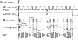
Fig. 3. Timing diagram for LMI.
Download figure:
Standard image High-resolution image2.2.1. Detection sensitivity of LMI
In LMI, the magnitude of tissue deformation corresponds to the tissue stiffness in the oscillated region. When the coagulation size and oscillated region size are almost the same, it is assumed that the detection sensitivity is high. In contrast, when the coagulation size and oscillated region size are different (i.e., the coagulation size is smaller or larger than the oscillated region size), the detection sensitivity or the accuracy of the estimated size is not sufficient for a size control.
Therefore, experiments were conducted to compare the coagulation size estimated by LMI with that measured with a ruler after HIFU ablation. HIFU ablation time and the temperatures of water and liver tissue were controlled using a constant-temperature water tank (EYELA NCB-1200) to create lesions of various sizes. We report here, a detection sensitivity related to an AM frequency of 168 Hz. In a typical case, the shear velocity of the tissue is 1 m/s. Under these conditions, the wavelengths of the shear waves were 10 and 5 mm at AM frequencies of 100 and 200 Hz, respectively. In this study, the target coagulation size to be detected is between these wavelengths. In addition, the displacement at higher AM frequencies were too small to be detected based on the cross-correlation. In consideration of these observations, an AM frequency of 168 Hz was selected. HIFU frequency and intensity at focus in water were 2.2 MHz and 1.2 kW/cm2, respectively. HIFU ablation periods were 15, 20, 30, and 45 s, and temperatures were 10, 20 (room temperature), and 35 (body temperature) °C. The beam propagation distance between the liver surface and the focal point of HIFU transducer was 20 mm.
The sampling frequency of the US equipment and the frame rate of the US scanner were 20 MHz and 436 Hz, and 28 frames (correspond to 2 periods of LMI oscillation) of RF data were acquired in every 1 s. The target was porcine liver tissue embedded in polyacrylamide gel. The RF data were processed off-line. The schematic of the experimental setup for off-line LMI is shown in Fig. 4.

Fig. 4. Schematic of experimental setup for LMI.
Download figure:
Standard image High-resolution image2.2.2. Development of real-time feedback control system
A real-time, one-dimensional LMI monitoring system using a ring buffer memory was constructed. Signal and image processing were implemented with Matlab code on a windows-based PC. On the basis of real-time LMI, a prototype feedback control system was constructed. The schematic of this system is shown in Fig. 5.
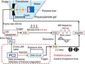
Fig. 5. Schematic of experimental setup for real-time feedback control system using LMI.
Download figure:
Standard image High-resolution imageSixteen frames (corresponding to one period of LMI oscillation) of RF data obtained by an ultrasound scanner were acquired within 0.05 s in every 1 s. The computation time for data processing including cross-correlation was within 0.9 s. This sequence is shown in Fig. 6. HIFU ablation time was controlled using a gate circuit based on the results of LMI. The target was porcine liver tissue embedded in polyacrylamide gel. The experiments were conducted at room temperature. In this experiment, the AM frequency was 168 Hz. The HIFU frequency and intensity were 2.2 MHz and 1.2 kW/cm2, respectively. The beam propagation distances L shown in Fig. 7 are 10, 20, and 30 mm. The experiments were conducted as follows:
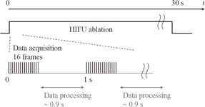
Fig. 6. Timing diagram for real-time measurement.
Download figure:
Standard image High-resolution image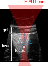
Fig. 7. Beam propagation distance L on a B-mode image.
Download figure:
Standard image High-resolution image- 1.HIFU ablation for 30 s without real-time feedback control.
- 2.HIFU ablation with real-time monitoring and feedback control until the coagulation length was greater than 10 mm.
In both cases, the coagulation areas were removed by cutting the target livers after HIFU ablation, and coagulation lengths were measured with a ruler.
3. Results
3.1. Detection sensitivity of LMI
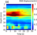
Figure 8 shows (a) an M-mode image of LMI displacement map and (b) an image of a normalized LMI displacement map. The horizontal and vertical axes are the time axis and the distance from the surface of the target sample in the depth direction, respectively. The focal point in the propagation direction is located at a depth of 17 mm [indicated by the solid line in Figs. 8(a) and 8(b)]. In an M-mode image, the tissue deformation occurred near the focal region and the magnitude decreased over time. To detect the beginning of coagulation and the formation of a coagulated region, measured displacement was normalized by the initial displacement at each depth. Figure 8 indicates a decreased ratio, and the coagulation size was estimated from the decreased region using a threshold of 0.8 (i.e., less than 80% of the initial displacement). Growth of the coagulated area is observed in this image.
Download figure:
Standard image High-resolution image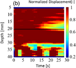
Fig. 8. (a) M-mode image of LMI displacement map and (b) image of a normalized LMI displacement map (L = 20 mm, 20 °C, 30 s ablation).
Download figure:
Standard image High-resolution imageFigure 9 shows the results from 49 data sets. The horizontal and vertical axes are coagulation size measured with a ruler after HIFU ablation and estimated by LMI, respectively. The closer the data point to the diagonal line are estimated with higher accuracy.
Fig. 9. Results of coagulation sizes measured with a ruler and estimated by LMI.
Download figure:
Standard image High-resolution image3.2. Real-time feedback control system
Examples of real-time LMI images are shown in Fig. 10. Maps of tissue displacement and normalized displacement are shown in Figs. 10(a) and 10(b), respectively. In this case, on-line LMI images were updated before the start of the next data acquisition. Simultaneously, the times for calculation including data transfer and displaying LMI were measured in each step; the results are shown in Fig. 11. The average and maximum calculation times were approximately 600 and 850 ms, respectively.
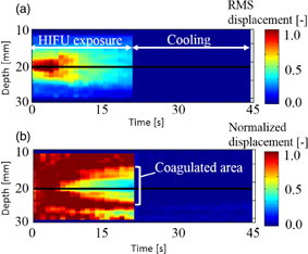
Fig. 10. LMI maps of real-time measurement (L = 20 mm, 20 °C, 20 s ablation).
Download figure:
Standard image High-resolution image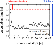
Fig. 11. Calculation time of real-time LMI for each step.
Download figure:
Standard image High-resolution imageOn the basis of these results, a prototype real-time feedback control system was constructed, and experiments using this system were conducted. The detection of the onset of coagulation is expected to be useful for exposure control in HIFU, and the real-time estimation of coagulation length in the US propagation direction is expected to be practically useful for lesion control in HIFU. Figure 12 shows LMI maps with real-time feedback control. During HIFU ablation, the tissue displacement could be measured. The results of the coagulation lengths after ablation with a constant ablation time of 30 s and feedback control based on real-time monitoring are shown in Fig. 13. The horizontal and vertical axes are the beam propagation distance and coagulation size measured with a ruler, respectively. The circles and asterisks in this figure indicate the results with constant ablation time and feedback, respectively. The dotted line indicates the targeted coagulation length. When the HIFU ablation time was constant, the coagulation lengths depended on the beam propagation distance (i.e., attenuation, and scatter). In contrast, when the HIFU ablation time was controlled by our system, the coagulation lengths were close to 10 mm. The average coagulation sizes and the average ablation times are shown in Table II. The size of the error for the short beam propagation distance (L = 10 mm) was reduced to 10% from 22%. The size of the error for the long beam propagation distance (L = 30 mm) was reduced to 14% from 35%. The standard deviations of the entire data set (calculated using the total of L = 10 and 30 mm) with constant time ablation and feedback control were 2.98 and 1.37, respectively. This result demonstrated that our prototype feedback control system could reduce the variation in coagulation size. In addition, the average ablation times for the short and long beam propagation distances were 25.2 and 35.2 s, respectively.

Fig. 12. LMI maps of real-time feedback control experiments (L = 30 mm, 20 °C, feedback control ablation).
Download figure:
Standard image High-resolution image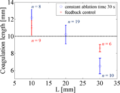
Fig. 13. Comparison between constant time ablation and feedback control.
Download figure:
Standard image High-resolution imageTable II. Average coagulation lengths and HIFU ablation times in the case of beam propagation lengths 10 and 30 mm.
| Average coagulation length (mm) (SD) | Average ablation time (s) | |
|---|---|---|
| 10 mm | ||
| Constant ablation time | 12.2 (±0.94) | 30 |
| Feedback control | 11.0 (±0.88) | 25.1 |
| 30 mm | ||
| Constant ablation time | 6.5 (±0.92) | 30 |
| Feedback control | 8.6 (±0.43) | 35.2 |
4. Discussion
4.1. Evaluation of detection sensitivity
To evaluate the detection sensitivity of LMI with an AM frequency of 168 Hz, root mean square errors (RMSEs) were calculated for each data section. The RMSE that indicates the reliability index is described as

where Xi is the measured coagulation size, xi is an estimated coagulation size, and n is the number of sample. The results of RMSE and sample numbers in each data section are shown in Fig. 14. Figure 14 shows that region of the actual coagulation size does not correspond to the estimated coagulation size in the area of small coagulation sizes. Tissue deformation magnitude corresponds to the average tissue stiffness in the oscillated region. Therefore, when the coagulated region was smaller than the oscillated region, the RMSE was large. On the other hand, LMI can measure tissue deformation only in oscillated regions. Therefore, the RMSE was also large when the coagulated region was larger than the oscillated region.

Fig. 14. LMI accuracy in each data section.
Download figure:
Standard image High-resolution imageThe RMSE has a small value in the data section for 8–12 mm. In this section, LMI has a high sensitivity for detecting tissue coagulation. Even if the coagulation size is close to that of the oscillated region, there is variability. As a result, the current LMI measurement accuracy has an absolute error of approximately 2 mm. Furthermore, the average of all relative errors in this data section was 16%. In these experiments, the same tissue samples were used to compare actual lesion size directly with estimated size without variation among the samples. Therefore, the accuracy is a measurement error in LMI due to the disturbance of the oscillation caused by tissue heterogeneity, such as the presence of blood vessels.
4.2. Evaluation of real-time feedback control system
Using the real-time LMI system, on-line LMI images were updated every 1 s. When the coagulation size was 10 mm, the coagulation area expands at approximately 0.2 mm/s. Therefore, the temporal resolution of this system is sufficient to control coagulation size. Furthermore, oscillation data in 2 periods were acquired and analyzed in these experiments. To improve the speed of processing, only 1 period of oscillation data was used; in this case, the noise negatively effects the LMI images. When acquired data numbers are equal to an integral multiple (N times) of 1 period, the signal-to-noise ratio (SNR) is calculated:

Repeatedly measured signals are added, signal components are N times, and noise components are  times. Because the oscillation data were reduced to 1 period from 2 periods, SNR is
  times. LMI images are not significantly affected by noise. There is a trade-off between temporal and spatial resolutions. In this case, temporal resolution is more important for the feedback control system. However, it is necessary that the data processing system be improved by use of a graphical processing unit (GPU) to improve both temporal and spatial resolutions.
In the case of a constant ablation time of 30 s, the coagulation size was approximately 10 mm for the US propagation distance of 20 mm. However, with the same ablation time, the coagulation size for the short propagation distance of 10 mm increased, which the coagulation size for the long propagation distance of 30 mm decreased. The cause of these results is the attenuation of US energy corresponding to the propagation distance. In actual treatment, the depth of tumor tissue and the acoustic properties of the US beam are different for each patient. Therefore, these variabilities in coagulation size can cause unnecessary damage to normal tissue and the risk of undertreatment for the entire tumor.
In contrast, with a feedback control system, the coagulation sizes were close to the targeted size of 10 mm for each propagation distance. The size errors in both cases are reduced to less than 15%. In the case of the short beam propagation, the estimated sizes of coagulations were larger than their target size. In the current experimental setup, it took 2 or 3 s to stop HIFU sonication after the estimated coagulation size reached 10 mm. This system delay caused an overdose and a size error in the coagulation. A current software implementation using Matlab has the possibility of causing system delay. In the future, more reliable and fast signal processing methods should be developed for the real-time control system.
On the other hand, in the case of the long beam propagation, the radiation force of HIFU and tissue deformation are both reduced owing to the attenuation of the HIFU beam. In the proposed method, all pixels for which the decrease ratio was less than 0.8 were counted as a coagulated area in the region of interest (ROI), as shown in Fig. 12. Therefore, the irrelevant region was counted as a coagulated region. In the result, the average estimated coagulation size for the long beam propagation was smaller than the actual coagulated size. In the future, a noise reduction algorithm will be implemented in the system.
4.3. Medical applications of LMI
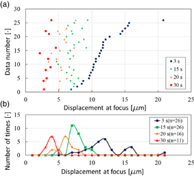
One use for LMI is to measure coagulation size during HIFU treatment. As mentioned, LMI is a method of measuring coagulation size using the change in tissue displacement before and after coagulation at the same position during HIFU ablation. To detect tissue coagulation, a method using cross-correlation between before and after B-mode images during HIFU treatment has been studied. In this method, the coagulated region is estimated by a change in brightness in B-mode images at the same position. Therefore, when monitoring positions were misaligned, the detection of a coagulated area was difficult. In contrast, LMI is based on a change of physical properties of living tissue. Consequently, another use for LMI is therapy evaluation after HIFU treatment. The HIFU beam induces irreversible thermal coagulation in living tissue, and LMI detects an average elastic modulus before and after thermal coagulation in an oscillated area as a tissue displacement. When LMI displacements in normal and coagulated tissue are dramatically different, LMI can assess a treated area in normal tissue using the scanning HIFU transducer operating on low power over a short time without thermal coagulation. When tissue displacement is large, the measured area is normal tissue. In contrast, when tissue displacement is small, the measured area is coagulated tissue. Figure 15(a) shows tissue displacements at focus measured by LMI (n = 26). In this case, the AM frequency was 168 Hz. The HIFU ablation times were 15, 20, and 30 s. The horizontal and vertical axes are displacement at focus and the data number, respectively. Blue, green, orange, and red points represent the displacement at 3 (before coagulation), 15 (beginning of coagulation), 20, and 30 s after the start of HIFU ablation, respectively. The tissue displacements after coagulation tended to decrease compared with those before coagulation. Figure 15(b) shows a histogram of the data in Fig. 15(a). The horizontal and vertical axes are the displacement at the focus and the number of times, respectively. The displacement distribution at 15 s overlaps with that at 3 s. In contrast, the displacement distribution at 30 s does not overlap with that at 3 s. These results show that tissue displacements can be separated by sufficient coagulation. Therefore, LMI has the potential to assess a treated area after HIFU treatment based on the difference in absolute displacements. Currently, HIFU treatment is allowed only for a benign tumor. In contrast, in the case of HIFU treatment for a malignant tumor, it is desired to treat the whole targeted region without leaving tumor behind. Therefore, it is important that a treated area and the surrounding tissue are assessed after HIFU treatment. Our proposed LMI method is expected to be a suitable assessment method.
Fig. 15. (a) Tissue displacement at focus measured by LMI in each sample and (b) a histogram of those data (L = 20 mm, 20 °C).
Download figure:
Standard image High-resolution image
4.4. Processing speed of LMI
The current computation time for LMI is about 0.9 s and the frame rate of LMI was 1 frame/s. Typical acquisition time of MRI thermometry is a few second. In this aspect, the imaging speed of LMI was not high. However, the data acquisition time for LMI was less than 10 ms for one data set. Therefore, LMI has the potential to be more than 100 times faster in its frame rate in principle. The signal process was calculated by Matlab code in a single CPU system. If the combination of a GPU for parallel processing and C code were to be used, this estimation of speed-up can be thoroughly realized. The current ratio of the rest time to the imaging period was only 17%. Therefore, if the time interval of between two 28-frame acquisitions is shorten, the efficiency of vibration and treatment is almost unchanged.
5. Conclusions
In noninvasive HIFU treatment, visualizing the treated area is necessary to control the HIFU exposure. LMI based on US imaging is one of the techniques capable of detecting a change in tissue stiffness caused by thermal coagulation during HIFU treatments. Experiments with porcine liver were conducted, and the current LMI measurement accuracy using an AM frequency of 168 Hz was an error of approximately 2 mm. Furthermore, the average of each relative error was 16%.
On the basis of this results, we have developed a prototype feedback control system using real-time LMI. In this system, coagulation size was measured every 1 s, and the HIFU ablation time was controlled. The coagulation size could be controlled by this system. The typical error was reduced to 14% from 35% in the case of the long beam propagation distance in tissue (30 mm).
The LMI displacements in normal and coagulated tissue were significantly different. A treated area in normal tissue can be detected and compared with absolute LMI displacement before and after coagulation. LMI is expected to be used in therapy evaluation after HIFU treatment.
Acknowledgment
This work was partially supported by Creation of Innovation Centers for Advanced Interdisciplinary Research Areas Program of MEXT, Japan.