
Abstract
The microvasculature presents a particular challenge in physiological measurement because the vessel structure is spatially inhomogeneous and perfusion can exhibit high variability over time. This review describes, with a clinical focus, the wide variety of methods now available for imaging of the microvasculature and their key applications. Laser Doppler perfusion imaging and laser speckle contrast imaging are established, commercially-available techniques for determining microvascular perfusion, with proven clinical utility for applications such as burn-depth assessment. Nailfold capillaroscopy is also commercially available, with significant published literature that supports its use for detecting microangiopathy secondary to specific connective tissue diseases in patients with Raynaud's phenomenon. Infrared thermography measures skin temperature and not perfusion directly, and it has only gained acceptance for some surgical and peripheral microvascular applications. Other emerging technologies including imaging photoplethysmography, optical coherence tomography, photoacoustic tomography, hyperspectral imaging, and tissue viability imaging are also described to show their potential as techniques that could become established tools for clinical microvascular assessment. Growing interest in the microcirculation has helped drive the rapid development in perfusion imaging of the microvessels, bringing exciting opportunities in microvascular research.
Export citation and abstract BibTeX RIS
1. Introduction
The microvasculature presents a particular challenge in physiological measurement because the vessel structure is spatially inhomogeneous and perfusion can exhibit high variability over time. The ideal instrument for evaluating the microvasculature would be able to perform imaging over a large surface area at rapid frame rates.
This clinically-focussed review serves as a primer to help clinical scientists, technologists or clinicians identify the capabilities of established microvascular imaging techniques. Future opportunities afforded by a number of emerging microvascular technologies are also discussed.
All the measurement techniques covered in this review are optical-based, using wavelengths from the ultra-violet to the far infrared. Specific wavelengths can reveal different structures and physiological information. Knowledge of the optical properties of tissue and the complex light–tissue interaction processes are important for an understanding of the imaging techniques, and the reader is directed to the recent review by Jacques (2013) for further information on more theoretical aspects.
Optical imaging techniques are non-ionizing and generally are less expensive and bulky than other established imaging modalities such as magnetic resonance imaging (MRI) and computed tomography (CT) (Mertz 2013, Vo-Dinh 2013). Portable optical imaging systems are now being developed which make microvascular measurement techniques easily accessible at the bedside. They enable monitoring of microvascular structure and blood volume, oxygenation and flow in tissue, where unusual patterns and changes on provocation can reveal early pathology. Some technologies are available in local spot measurement format, providing serial quantification of perfusion or temperature at a single point. However, imaging has numerous advantages over point measurements: the techniques are commonly non-contact, information can be collected simultaneously from a large tissue surface area, and the results of the test can be communicated more easily to the clinician and patient.
This paper is in two main parts. Firstly, the four established imaging technologies laser Doppler perfusion imaging (LDPI), laser speckle contrast imaging (LSCI), thermal imaging and nailfold capillaroscopy (NFC) are introduced. Then we describe five key emerging technologies in microvascular assessment: imaging photoplethysmography (iPPG), optical coherence tomography (OCT), photoacoustic tomography (PT), hyperspectral imaging (HSI), and tissue viability imaging (TiVi). These were chosen as they were considered to be representative of the technology landscape for clinical applications. The modalities covered are not exhaustive and readers can find information on other developments, particularly for microscopic techniques, including diffraction-limited methods (e.g., confocal microscopy and 2-photon microscopy) (Dhawan et al 2010, Chen et al 2012).
The current and potential applications for microvascular imaging are vast and include vascular surgery, rheumatology, neurology, immunology, dermatology, plastic surgery and burns, cancer, stroke medicine, diabetes, and chronic pain. The range is clearly very diverse and so the right technology needs to be chosen for a particular clinical application. We hope this review will help inform the practitioner in this respect.
2. Standard techniques used in the clinical microvascular laboratory
2.1. Laser Doppler perfusion imaging
2.1.1. Background
Laser Doppler flowmetry (LDF) uses the frequency shift of low-power (typically in the region of 1 to 5 mW and single mode) laser light produced by the Doppler effect to assess tissue blood flow (Oberg et al 1979). The initial development was single point measurement technology using fibre-optics, with developments in imaging coming to fruition in the early 1990s (Essex and Byrne 1991, Wårdell et al 1993). Depending on the laser wavelength employed, LDF can assess blood flow in the nutritional capillaries close to the skin surface and the underlying arterioles and venules deeper in the dermis involved in regulation of skin temperature (figure 1). LDF could also be used for other tissues when exposed at surgery, e.g. colonic blood flow (Hajivassiliou et al 1998). The tissue thickness sampled by a red or infrared laser system is typically 1 mm, the capillary diameters 10 µm and the erythrocyte velocity range 0.01 to 10 mm s−1. Blood flow information can also be available for the larger elements of the microvasculature, i.e. 100 µm, although LDF underestimates flow when these vessels are vasodilated due to system bandwidth limitations.
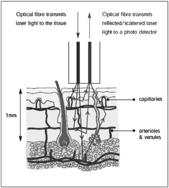
Figure 1. Dermal layers and microcirculation probed by laser Doppler techniques. (Courtesy of Moor Instruments.)
Download figure:
Standard image High-resolution imageThe technique depends on the Doppler principle whereby low power light from a monochromatic stable laser e.g. a 633 nm helium neon gas laser or a single mode 670 or 780 nm laser diode, incident on tissue is scattered by moving red blood cells and as a consequence is frequency-broadened. The frequency-broadened light, together with laser light scattered from static tissue, is photo-detected, and the resulting photocurrent is processed. The high spatial variability in blood flow across tissue such as the skin limits the clinical utility of single point LDF measurements. However, this limitation can be overcome with LDPI which provides a two-dimensional colour-coded representation of blood flow for the imaged tissue (figure 2(a)). Furthermore a key advantage of LDPI is that it is non-contact and the target tissue size can be configured to optimize the spatial resolution. Typical square field sizes range from a few centimetres up to 0.5 m (figure 2(b)).
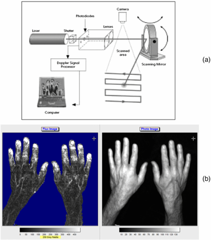
Figure 2. (a) Schematic diagram of raster scanning based LDPI technology. (b) Example of LDPI of the hands alongside a visible light image. The increased perfusion is easily seen through the finger nails and on the edge of the thumb. The perfusion scale is also shown. (Courtesy of Moor Instruments.)
Download figure:
Standard image High-resolution imageBriers (2001) provided an excellent topical review on LDPI technology and applications for blood perfusion mapping and imaging for the formative years of the technique. His review also described the theory for the measurement of blood flow changes in the microvasculature. Laser Doppler imaging technology is now available in several forms, using the traditional raster scanning method and more recently line scanning technology (Nguyen et al 2011) and full-field imaging capability (Serov and Lasser 2005, Leutenegger et al 2011, He et al 2012) (figure 3). The imaging systems usually use a single operating wavelength, i.e. red or near infrared. Murray and co-workers (2004, 2005, 2009a) have shown the clinical value of using a red wavelength LDPI system in conjunction with a green laser and this is discussed further below.
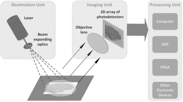
Figure 3. Schematic diagram for full-field laser Doppler imaging technology concept. This approach enables fast scanning of areas such as the hands and synchronous changes across the field of view to be determined with confidence. (Courtesy of Professor S Morgan, Nottingham University.)
Download figure:
Standard image High-resolution imageThe full-field fast scanning LDPI systems are relatively new to the market and so much of the evidence base for clinical applications lies with the raster line scanning systems.
2.1.2. Clinical applications of LDPI
LDPI has been applied extensively in clinical and research studies with reported applications in burn depth assessment, dermatology and plastic surgery, inflammation, wound healing, rheumatology, diabetes, pain, endothelial function assessment, cancer and angiogenesis. Fullerton et al (2002) provides guidelines on standardization in LDPI methods. Klonizakis et al (2011) address the reproducibility of microvascular measurements using laser Doppler techniques.
Burn wound depth assessment.
It is important clinically to determine if a burn is deep or superficial as this affects the choice of treatment. A deep burn usually requires grafting, whereas a superficial burn with skilled conservative management can heal on its own within 21 days without costly surgery. In deep tissue burns, the dermal layers and associated vasculature are damaged and so the hyperaemic blood flow response in normal wound healing is disrupted. A reliable hyperaemia will be present or absent after about 48 h post burn for superficial dermal or deep dermal burns, respectively, and use of LDPI to assess this (figure 4) has been validated, until 5 days post burn, by Monstrey et al (2011) and Pape et al (2012). LDPI can detect the microvascular blood flow in the dermis and, when used within this timeframe, can detect the presence of hyperaemia and thus give objective evidence for a burn being classed as deep or superficial (Hoeksema et al 2009, Pape et al 2012).
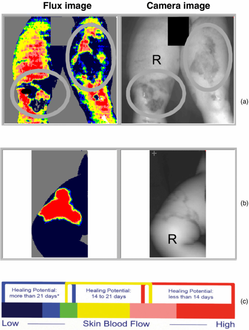
Figure 4. (a) Deep dermal burns can be clearly seen in the circular regions of interest on the legs and (b) a superficial dermal burn with (c) scale guide indicating the healing potential in days. (Courtesy of the Department of Plastic & Reconstructive Surgery, Ghent University Hospital.)
Download figure:
Standard image High-resolution imageLDPI is now a widely accepted tool to assess burn depth, with an ever-increasing body of evidence to support its use, as described in reviews (Devgan et al 2006, Sainsbury 2008, Monstrey et al 2008, Sharma et al 2011). The National Institute for Health and Clinical Excellence (NICE) (2011) provided evidence of clinical benefit and cost saving when LDPI (specifically for the Moor Instruments moorLDI2-BI imaging system) was used to guide treatment decisions for patients in whom there was uncertainty about burn depth and healing potential. This was a reliable endorsement to support both the clinical efficacy and health economics of the technology.
Dermatology and plastic surgery.
There have been many papers published on the assessment of microvascular perfusion in the skin including psoriasis (Speight et al 1993, Krogstad et al 1995, Murray et al 2005), scarring (Peeters et al 2012), skin flap viability (Payette et al 2005), telangiectasia (Murray et al 2009a), cutaneous inflammatory reactions (Harrison et al 1993, Clough et al 2001, Sharif et al 2012) and port wine stain (PWS) birthmarks (Huang et al 2009). This shows the great versatility of LDPI.
Surgery and wound healing.
LDPI is of value for assessing tissue perfusion in healing of wounds, and the changes following surgical procedures. Good blood supply is a key determinant for wound healing, with chronic wounds often occurring in the legs. An excellent review of LDPI and lower limb wounds given by Khan and Newton (2003) covers a range of wound types, healing mechanisms, treatment effects, risk prediction, healing potential, and underlying pathology. A significant number of studies involve animal models to help understand healing mechanisms.
Lyung et al (1995) reported good wound healing after total elbow joint replacement in rheumatoid arthritis from 42 patients when elbows were immobilized for 12 days. Furthermore, pre- and post-operative LDPI assessments in a sample of five patients from the group were compared and showed that post-operative perfusion was considerably higher than before surgery.
Pre-arterial sympathectomy is a surgical procedure where specific nerves are chemically inactivated, thereby removing sympathetic tone and leading to vasodilatation to improve peripheral blood flow in patients with vaso-occlusive disease. It can also result in pain relief, improved quality of life, healing of ulcers and raised peripheral skin temperature. However, its benefits are not always long-lasting and the mechanism involved is not fully understood. Pollock et al (1997) studied peripheral blood flow following sympathectomy in a rabbit ear model of digital microcirculation (arterioles, arteriovenous anastomoses, and venules). The study showed the central auricular artery became dilated (50–100%) immediately after sympathectomy, with LDPI perfusion increasing by approximately 200% within 30 to 60 min of the procedure. The ear temperature increased by 3 °C but with no fall in core temperature.
The effect of hyperbaric oxygen therapy on microvascular perfusion of wounds in normal and ischaemic tissue has been investigated using LDPI by Uhl et al (1994). They used a standardized animal model (the ears of mice). Baseline perfusion measurements were compared with those recorded during therapy (100% oxygen at two atmospheres of absolute pressure), and the results showed that the therapy improved wound healing clinically but this was not mirrored by LDPI blood flow measurements. Hyperbaric oxygen would not necessarily be expected to lead to an increase in perfusion, but as the blood flow to the periphery could transport more oxygen to the tissues this may have promoted healing.
Rheumatology.
There are a range of rheumatological conditions where the microcirculation and tissue perfusion are grossly affected (Herrick and Clark 1998). LDPI has been applied across the clinical spectrum to assess patients with Raynaud's phenomenon (RP) and connective tissue diseases including systemic sclerosis (SSc, also known as scleroderma) (Herrick and Hutchinson 2004, Anderson et al 2004), erythromelalgia (Mork et al 2000), fibromyalgia (Al-Allaf et al 2001), morphoea (localized scleroderma) (Moore et al 2009, Shaw et al 2013), myopathy (Gunawardena et al 2007), and joint inflammation and tennis elbow (Ferrell et al 2000).
RP is a vasospastic condition of the microvasculature characterized by phasic colour change, paraesthesia and numbness in the extremities (fingers or toes), in response to cold or emotional stimuli. Isolated (primary) RP is not uncommon, but more rarely it can be the early marker for an underlying medical condition, such as SSc. LDPI can assess finger blood flow at rest, and Raynaud's protocols usually evaluate the recovery in digital blood flow following a mild cold challenge to the hands. In healthy subjects the fingers should be well-perfused in a warm environment, and recover perfusion within a 10 min period following cold provocation. In RP the finger reperfusion response to mild cold challenge is usually significantly delayed and there are often differences in recovery between the digits. A feature of primary RP is that the thumbs can be spared relative to the fingers. The Salford group led by Professor Arianne Herrick has published extensively on LDPI (Clark et al 1999, Murray et al 2009a, 2009b) and made comparisons with other imaging modalities including thermography (Clark et al 2003).
One manifestation in SSc is the presence of dilated microvessels in the skin, particularly the hands and face, and these are known as telangiectasiae. Murray et al (2009a) employed dual wavelength LDPI; red light to probe the deeper tissue blood flow and green light to probe the more superficial blood flow. They showed that the apparent size of these vessels at the skin surface does not predict blood flow at deeper levels, indicating that the dual wavelength measurement may help predict treatment response. SSc is also commonly associated with digital ischaemia (painful ulcers on the fingers and toes) and diagnosis and follow-up of treatment to assess the response to therapy is important. The potential role of LDPI for follow-up of ulcers in SSc has been described by Rosato et al (2009).
Diabetes.
It is well established that the microcirculation, autonomic nervous system, and endothelial function can be significantly impaired in diabetic patients (Muris et al 2013). LDPI can be employed to assess each of these aspects. Microvascular blood flow is usually assessed in the extremities to quantify the perfusion in the toes, foot ulcers and wound healing (Newton et al 2001a). Sympathetic neuropathy and parasympathetic neuropathy are frequent in types 1 and 2 diabetes and Freccero et al (2004) using LDPI assessed sympathetic nerve function in diabetes. They developed a 'vasoconstriction index' by locally heating a finger followed by indirect cooling and showed that the nature of autonomic function damage was different between type 1 and 2 diabetes. Parasympathetic function was assessed by ECG R-R interval variation.
Endothelial dysfunction is described below in a variety of conditions but with the focus on diabetes it has been summarized by Morris et al (1995), Veves et al (1998), and Beer et al (2008).
Endothelial (dys)function.
Endothelial function can be assessed from a macrovascular perspective e.g. by testing the flow-mediated dilatation response of the brachial artery during post-cuff occlusion reactive hyperaemia, whereby a reduced maximal vessel opening is associated with endothelial dysfunction. Endothelial function can also be studied by focusing directly on the behaviour of blood flow in the capillary vessels (Newton et al 2001b, Beer et al 2008). The capillaries in the skin are made from endothelium, and as they are close to the surface, they are accessible for measuring the degree of vasodilatation in their locality on provocation (Clough 1999). LDPI imaging is suggested to offer signal-to-noise advantages over conventional non-imaging laser Doppler flowmetry (LDF) as it allows averaging over many imaging points to reduce the effect of spatial heterogeneity.
There are a range of protocols for testing endothelial function using LDPI and these include local skin heating (water heater placed on the skin site, usually the forearm, and with an optical aperture for blood flow imaging, figure 5), iontophoresis (vasoactive compounds pass through the skin on a low level dc current stimulation, usually acetylcholine for endothelial-dependent vasodilatation (Ach) and sodium nitroprusside (SNP) for endothelial-independent vasodilatation as a reference comparator) (Morris et al 1995, Anderson et al 2004, Turner et al 2008), and post-occlusion reactive hyperaemia (flush characteristics assessed after usually a 5 min arm pressure cuff occlusion of at least 250 mmHg). Each of these methods provides different information relating to the health of the endothelium. Choice of measurement site and measurement reproducibility are very important considerations (Kubli et al 2000), with a coefficient of variation typically of 17% found for acetylcholine iontophoresis with LDPI (Newton et al 2001b). Normative data are important to establish for each measurement facility, protocol, local study population and age range (Elherik et al 2003, Millet et al 2012).
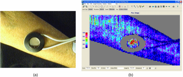
Figure 5. (a) Forearm skin measurement site with skin heater filled with heated water at set study temperature to achieve local vasodilatation (temperature set typically to 41 °C). The water chamber has a plastic cover which allows the laser system to measure the corresponding perfusion changes i.e. reactive hyperthermia (b). Over a heating period of typically 30 min an initial spike in perfusion is expected near the start of heating (attributed to the axon reflex) and then reaching a peak level. This heating type challenge test can also be measured using LDF spot perfusion techniques at the forearm microvasculature, and comparing peak perfusion during heating to baseline perfusion can give information on microvascular endothelial dysfunction, for example in patients with wider coronary heart disease (Agarwal et al 2010, 2012).
Download figure:
Standard image High-resolution image2.1.3. Other clinical applications
2.1.3.1. Chronic pain.
Dysfunction of the sympathetic nervous system is thought to be a factor in neuropathic pain conditions such as complex regional pain syndrome (CRPS). LDPI can be used to quantify changes in skin capillary blood flow which reflect activation of sympathetically-mediated vasoconstriction of the arterioles that supply the capillaries. Grothusen and Schwartzman (2011) provided case study reports of pain patients which suggested that bilateral LDPI monitoring of the deep inspiratory gasp reflex may be able to distinguish between sympathetically-mediated and sympathetically-independent pain. Gorodkin et al (2004) used LDPI to assess contralateral limb vasodilatory responses to ACh iontophoresis in CRPS patients and found no impairment in the patient group compared to healthy control subjects. Such studies demonstrate the wide utility of LDPI in allowing physiological mechanisms to be investigated, so that therapy may be better targeted and patient outcomes can be improved.
Cancer and angiogenesis.
Often animal model studies are performed to study perfusion in the processes of angiogenesis and tumour development (Kalka et al 2000, Iimuro et al 2004, Ferraro et al 2010), as well as studying responses to therapy (Yang et al 2009). These processes are not well understood but technologies such as LDPI can allow an optical window into the superficial microvascular layers, for example to study malignant melanomas (Patel et al 2008).
Brain and brain injury.
The optical penetration depth available in LDPI limits assessments to superficial tissue layers in open brain in humans. Nevertheless LDPI has been shown in various animal models to provide information on brain biochemistry (Broderick and Kolodny 2011), cerebral ischaemia (Liu et al 2001) and spatial-temporal characteristics of activation-flow coupling (Ances et al 1999).
Chronic fatigue syndrome.
Chronic fatigue syndrome (CFS) is a debilitating condition of unknown etiology. Various reports in the literature show links to autonomic dysfunction (Allen et al 2012), low grade inflammation and increased arterial stiffness (Spence et al 2008), and endothelial dysfunction but with an enhanced rather than diminished sensitivity of the peripheral cholinergic vascular response (Spence et al 2000).
2.2. Laser speckle contrast imaging
A significant limitation of LDPI is its slow data capture. Even with the fastest line-scanning devices, the frame rates are only a few frames per minute. Current commercially-available LDPI is therefore not suitable for providing information about microvascular haemodynamics at frequencies close to that of the cardiac cycle or vasomotion (Aalkjær et al 2011). In recent years this constraint has been overcome with the introduction to the market of laser speckle contrast devices, which offer a single-shot, full-field technique for the imaging of microvascular perfusion.
2.2.1. Background
Briers (2001), Cheng et al (2004) and Basak et al (2012) describe the principle of LSCI. Laser speckle arises from the interference pattern created when laser light is scattered from an illuminated surface. The speckle contrast of the pattern, K, is defined as the ratio of the standard deviation (σ) to the mean intensity (〈I〉):

which for scatter from a perfectly-diffusing (Gaussian) surface will be unity, but will be less than this in practice.
If there are moving scatterers associated with the illuminated surface (moving erythrocytes, for example), the speckles will become de-correlated over time and the contrast will vary. Integrating K over a short exposure time T (typically 20 ms) and across a small surface area (typically 5 × 5 pixels) allows an estimate of the speckle correlation time τc which will in turn be proportional to the velocity of the scatterers.
Figure 6 shows a theoretical plot of image contrast K against the ratio of correlation time to exposure time for a Lorentzian velocity distribution, whereby it is assumed the mean velocity is zero with an equal likelihood of positive and negative velocities. This would be a reasonable model to represent the random architecture of the microvasculature. Figure 6 also demonstrates how integration time T can be adjusted to select an appropriate range of erythrocyte velocities. It is necessary to operate along the steepest part of the curve to achieve the greatest sensitivity to change in perfusion.
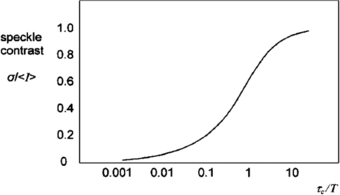
Figure 6. Speckle contrast (K) versus the ratio of speckle correlation time to exposure for Lorentzian flow (reproduced with permission from Briers 2001 Physiol. Meas. 22 R35–66).
Download figure:
Standard image High-resolution imageRecent improvements in processing power mean that computational time no longer limits the imaging rate, since it is shorter than the data acquisition time. Image resolution is reduced by the necessity for averaging over a 5 × 5 pixel window, but resolution in practice is normally limited by photon scattering under the tissue (Boas and Dunn 2010). Figure 7 shows a schematic configuration of a laser speckle contrast imager.
Figure 7. (a) Schematic representation of a basic design of laser speckle contrast imager (reproduced with permission from Briers 2001 Physiol. Meas. 22 R35–66). In (b) an LSCI high spatial resolution image of the hand from a modern Moor Instruments FPLI-2 full field laser perfusion imaging system. The flux scale is also shown.
Download figure:
Standard image High-resolution image2.2.2. Comparison of LSCI to other techniques
The laser-speckle contrast technique has been widely validated in vivo against other established methods of microvascular perfusion measurement.
Bezemer et al (2010a) showed a good correlation between LSCI and sidestream dark field microscopy at the human nailfold during gradual occlusion of the upper forearm, and subsequent reperfusion. A number of studies have investigated the equivalence of LSCI and laser Doppler techniques. Binzoni et al (2013) reported poor agreement between LSCI and point laser Doppler at the human forearm. Differences in readings may arise in part because of different measurement depths achieved by the two techniques. Tew et al (2011) demonstrated better reproducibility of post-occlusive reactive hyperaemia at the forearm with LSCI than with laser Doppler flowmetry, probably due to the larger surface area sampled with LSCI. Conversely, sympathetic vasomotor reflexes at the finger pad (deep inspiratory gasp, cold pressor test) were more reproducible with laser Doppler flowmetry than with LSCI.
Millet et al (2011) compared LSCI with LDPI in the assessment of skin blood flow at the human forearm. LSCI showed lower inter-site variability of basal blood flow than LDPI, probably due to the deeper penetration of LDPI into the tissue, thus sampling the high-variability blood flow in forearm veins. There was a good correlation between the two techniques overall, but there was a proportional bias between the methods that limited their agreement.
Mahé et al (2012) have reviewed the use of LSCI for the assessment of skin microvascular function and dysfunction, commenting in particular on the high reproducibility of speckle contrast techniques in comparison to laser Doppler modalities.
2.2.3. Clinical applications of LSCI
LSCI has been applied extensively in human (and animal) studies of cutaneous, cerebral and renal blood flow.
Skin microvasculature.
LSCI is becoming an important tool in the study of wound healing. Using an animal model Du et al (2011) studied the skin blood flow in 20 skin flaps in rats with LSCI. They compared a control flap group to a group in which the flaps had undergone a vascular delay procedure, which is known to enhance neovascularization and increase flap survival. LSCI showed that flow speed in the flaps increased after the delay procedure. In a mouse ear model, Rege et al (2012) studied skin perfusion after injury with LSCI, validating the results with histology. A measure of microvessel density increased in the first three days after injury, remained elevated through to day 7, before falling to baseline levels by day 12. Speckle blood flow measurements showed an initial reduction in perfusion after injury in the wound periphery, followed by an increase between days 3 and 7 and then normalization of flow as healing completed.
Good reproducibility for laser-speckle assessment of the response to post-occlusive reactive hyperaemia and local thermal hyperaemia at the human forearm has also been reported (Roustit et al 2010). Cordovil et al (2012) recorded blood flow at the forearm with LSCI in 50 healthy human subjects, and 50 patients with cardiometabolic disease. LSCI was able to detect the reduced endothelium-dependent vasodilator responses to acetylcholine administration and forearm occlusion in the cardiometabolic disease group.
Laser Doppler techniques are of proven utility in the assessment of skin burns, and interest has inevitably developed in laser speckle evaluation of burns. Lindahl et al (2013) measured perfusion in skin burns 0–14 days after the burn in 45 children using LSCI, comparing the blood flow to 32 uninjured areas. Burns that healed within 14 days were found to have a higher perfusion than those that took greater than 14 days to heal, or ultimately required surgery.
Qiu et al (2012) monitored skin blood flow with LSCI in PWSs before and after targeted vascular photodynamic therapy. A transient increase in blood flow was generally observed with the rise in skin temperature during treatment.
Cerebral and stroke.
The ability of LSCI to map microvascular blood flow in real-time across much of an organ's surface has attracted great interest from brain, neurosurgical and stroke research groups.
Using an animal model Royl et al (2006) measured blood flow in the rat somatosensory cortex with both LSCI and laser Doppler flowmetry. They found that the magnitude of changes in cerebral blood flow measured by the two techniques correlated well. Armitage et al (2010) used LSCI to map collateral blood flow after middle cerebral artery occlusion, also using a rat model. They were able to detect anastomotic connections that developed between brain vessels after the occlusion, which persisted for 24 h. Levy et al (2012) have demonstrated the utility of a LSCI method in combination with blood oxygenation measurements in experimentally induced brain ischaemia in rats.
Dunn (2012) has reviewed LSCI and its application to stroke research and intra-operative real-time monitoring of human brain blood flow in neurosurgery. Parthasarathy et al (2010) adapted a neurosurgery operating microscope to obtain intraoperative laser speckle images from humans before and during bipolar cautery. The cauterization process gave rise to a reduction in cerebral blood flow, followed by a transient increase in perfusion. ECG waveforms from the patient were used to filter the speckle signal for the reduction of motion artefacts.
Renal.
Autoregulation of microvascular haemodynamics and the effects of ischaemic injury are important topics in renal research where LSCI may be of utility.
Bezemer et al (2010b) mapped regional differences in renal reperfusion in rats using LSCI after varying durations of ischaemia. They found that LSCI measurements correlated well with single-point laser Doppler velocimetry.
Holstein-Rahlou et al (2011) used LSCI to investigate the autoregulation of blood flow in nephrons in a rat model. By measuring from 50–100 nephrons simultaneously at the renal surface, they were able to detect synchronized blood flow oscillations in pairs or triplets of nephrons. The synchronized nephrons were not always nearest neighbours, and were instead some distance from each other across the surface of the kidney.
2.2.4. Other clinical applications
Fukuoka et al (1999) used a laser-speckle technique during surgery to measure blood flow in the subchondral bone of the femoral head in 100 patients with osteonecrosis. LSCI was able to distinguish the ischaemic from normal tissue areas in 92 of the cases. LSCI is also of utility in the assessment of blood flow in articular tissues. Miller et al (2010) described the measurement of blood flow in the medial collateral ligament in a rabbit model of anterior cruciate ligament deficiency. Other potential applications include thyroid eye inflammatory disease in endocrinology. An example of this is shown in figure 8 for a patient with the active form of the disease. Determining if inflammatory activity around the eyes is significant gives valuable care pathway information. Active patients are treated with anti-inflammatory medication rather than corrective surgery (which should only be done when the patient is not active).
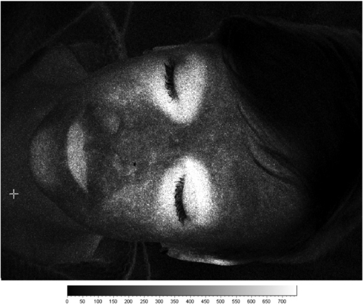
Figure 8. Example laser speckle contrast image of a patient with active thyroid eye disease. There are significantly elevated flux levels around each eye and consistent with inflammation.
Download figure:
Standard image High-resolution image2.3. Thermography
Changes in tissue perfusion often result in a change in tissue temperature. This is the principle of thermography for microvascular imaging: it uses an infrared thermal imaging camera to determine tissue temperature from the human body. Figure 9 shows examples of false-colour thermograms recorded from various skin sites using a modern 320 × 240 pixel thermal imager.
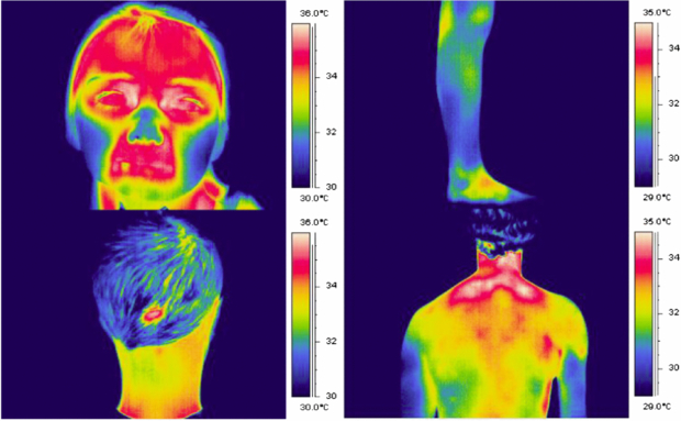
Figure 9. Example thermograms of the temperature distribution of the human body, recorded using the FLIR SC500 thermal imager (320 × 240 pixels, 7–14 µm waveband).
Download figure:
Standard image High-resolution image2.3.1. Background
All objects at a temperature above absolute zero emit energy according the Stefan–Boltzmann law (Ring et al 2009). If an opaque surface at absolute temperature Tabs is imaged against an absolute background temperature Tbgrd, the detected power Q is calculated from:

where σ is the Stefan–Boltzmann constant (5.67 × 10⁻⁸ Wm−2 K−4), A is the surface area of the object, and ε is the emissivity of the material: a correction factor ranging from 0 to 1 that indicates how well an object emits radiant energy.
A theoretical perfect emitter would have an emissivity of unity: such an emitter is known as a blackbody. Human skin has been shown to behave very similarly to a blackbody (Sanchez-Marin et al 2009), making the human body an efficient infrared radiator.
The above expression calculates the power detected over all wavelengths, but a thermal imager will only be sensitive to infrared radiation across quite a narrow bandwidth, and as object temperature changes the amount of energy within the imager bandwidth will also change. Additionally, the response of the thermal detector and camera optics may not be flat over the bandwidth used. A more representative expression for the relationship between the temperature and the signal measured by a thermal camera detector would be:

with the nature of the temperature functions (f) derived experimentally for the detector used, and optimized for the temperature measurement range required.
2.3.2. Thermal imager specifications and quality assurance
Figure 10 shows a schematic for a typical thermal imager design. Incident radiation is focussed by a filter and lens arrangement onto the surface of an infrared detector system. This may consist of a single detector which is mechanically scanned across the field of view by a system of rotating mirrors or, more commonly in modern devices, it may comprise a large collection of 'staring' infrared detectors fabricated onto a single microchip. In this case there is a one-to-one correspondence between each detector on the array and each pixel within the output thermal image. Such detectors are termed focal plane arrays (FPAs) because the readout circuitry is incorporated onto the detector chip to provide complete processing of the image in the focal plane.
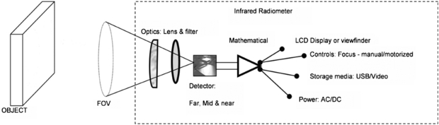
Figure 10. Schematic of a thermal imager (permission granted to re-use from Ring et al 2009 Sensors for Medical Thermography and Infrared Radiation Measurements (New York: Momentum)).
Download figure:
Standard image High-resolution imageThere is a wide variety of detectors available, which can operate in the 'far' (7.5–15 µm), 'mid' (2–5.6 µm) or 'near' (0.8–2 µm) thermal infrared wavebands. 'Photon' type detectors are doped semiconductors, with a current generated when infrared photons impinge on the detector and excite electrons across an energy gap. Such detectors require cooling to reduce noise (which complicates the imager design), but benefit from high thermal sensitivity. A less expensive solution is the uncooled microbolometer detector. Here, each detector in the array is heated by incident infrared radiation, causing a change in resistance. These detectors are typically of lower thermal sensitivity than their cooled counterparts, and are more prone to drift with change in ambient temperature. Nonetheless, refinements in design and fabrication have seen a radical improvement in uncooled detector performance in recent years.
Thermal imagers are generally not marketed as medical devices (sales are instead targeted at industrial and maintenance applications). This means that biomedical users of thermography must ensure procedures are in place in-house for rigorous quality assurance and calibration of the thermal imager (Howell and Smith 2009, Plassmann et al 2006). Objective assessment of performance also allows imagers to be compared, and the most appropriate device selected for clinical applications (Richards et al 2013).
2.3.3. Relationship between skin temperature and perfusion
The relation between skin temperature and microvascular dermal perfusion is complicated, and dependent on body site. Away from the periphery, skin temperature will be additionally strongly influenced by factors such as subcutaneous and muscle blood flow, skin thickness and perspiration. These in turn will be influenced by variables such as ambient temperature and core body temperature. A number of thermographic studies have investigated skin temperature across the body surface (Uematsu 1986, Zaproudina et al 2008, Goodman et al 1986). Howell et al (2009) compared temperature with laser Doppler blood perfusion at various skin sites.
In contrast, the acral areas play a key role in autonomic thermoregulation, and change in microcirculatory perfusion is the dominant driver of temperature change in glabrous (hairless) skin, which is richly populated with arteriovenous anastomoses. Figure 11 plots nose blood flow (monitored by laser Doppler flowmetry) against nose temperature as ambient temperature is varied across the range 15–40 °C. As ambient temperature rises above core body temperature, skin temperature is kept below 37 °C by a significant increase in skin blood flow. Seifalian et al (1994) gained a similar asymptotic relationship between skin blood flow and skin temperature by comparing laser Doppler perfusion with thermography measurements on hand skin.
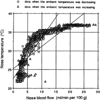
Figure 11. Nose blood flow versus temperature as ambient temperature is varied across the range 15–40 °C (permission granted to re-use from Mabuchi et al 1995 The Thermal Image in Medicine and Biology (Vienna: Uhlen)).
Download figure:
Standard image High-resolution imageAfter cold challenge of the hand, Pauling et al (2012b) found a good correlation in healthy subjects between thermography and hand skin perfusion as measured by the laser speckle contrast technique, and the correlation was strongest in glabrous skin. Buick et al (2009) also found a similarity between thermography and LSCI when measuring response to hand cold challenge at the fingertips. However the two techniques showed a different response to a skin scratch at the volar surface of the forearm: the speckle instrument revealed an inflammatory reaction at the scratch site, whereas thermography predominantly highlighted increased flow in nearby perforator vessels bringing blood flow to the scratch (figure 12).
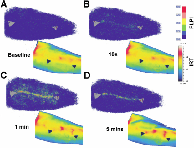
Figure 12. Evolution of laser speckle contrast perfusion (upper images) and skin temperature (lower images) after a scratch to the volar surface of the forearm (permission granted to re-use from Buick et al 2009 Thermol. Int. 19 43–6).
Download figure:
Standard image High-resolution imageMerla et al (2007) formulated a heat-flow model through the skin and were able to convert a thermal image into an image estimating cutaneous blood flow (in arbitrary units) at each pixel point. These cutaneous blood flow estimates correlated well at the dorsum of the hand with blood perfusion as measured by LDPI (laser wavelength 670 nm). No data was presented for the correlation between the two methods specifically at the glabrous skin of the fingertips.
2.3.4. Applications of thermography
2.3.4.1. Assessment of peripheral vasospasm.
Thermography has been widely used as a method for quantifying the re-warming rate of the fingers in vasospastic conditions such as RP after a cold challenge to the hand. Ring (1980) described a 'thermographic index (TI)' for ischaemia of the hand, calculated by summing isothermal areas relative to 24 °C, and expressed as a proportion of the total skin surface area measured. The TI was found to be an effective way of measuring small changes in response to cold challenge over time.
Ring et al (1981) studied the response to inositol nicotinate using cold challenge thermography in 20 RP patients treated over 36 weeks. Thermography showed an improvement in re-warming after cold challenge at 36 weeks compared to baseline.
Prostaglandins (i.e. types PGE1 and PGI2) have showed particular promise clinically. Martin et al (1981) performed a single-blind crossover study comparing 72 h of infusion of saline and prostaglandin PGE1 in 12 scleroderma patients. Hand thermograms were recorded daily during, and two weeks after, the infusions. Cold challenge was also performed immediately after the infusions. TIs for hand dorsum and fingers rose significantly on PGE1 compared to placebo, with the maximal difference after two days of infusion, but the authors were unable to demonstrate improvements to the cold challenge response on PGE1. The same research group also monitored responses to PGI2 infusion in 24 scleroderma patients across two centres: at one with an AGA 680 thermal imager and at another with a KT41 radiometer (Dowd et al 1982). They found thermography was able to demonstrate increasing finger and hand temperature during infusion, but this effect was shown less markedly using the radiometer. Kyle et al (1992), whilst reporting some therapeutic benefits of PGI2 infusion on a double-blind, placebo-controlled study, failed to demonstrate any improvement in the response to hand cold challenge over placebo. Shawket et al (1991), in a double-blind crossover study comparing infusions of PGI2 and calcitonin gene-related peptide (CGRP), concluded that CGRP improved the response to hand cold challenge three days after infusion, whereas PGI2 did not.
Coleiro et al (2001) monitored finger re-warming rates with thermography after cold challenge in a double-blind crossover comparison of fluoxetine and nifedipine for the treatment of RP. Thermography findings were in agreement with patient symptom diaries, and showed a statistically significant faster re-warming from cold challenge in the fluoxetine treatment arm in females with primary RP.
Despite these informative studies, the reproducibility and reliability of hand cold challenge as an outcome measure in RP remains unclear (Pauling et al 2012a). Further studies are required to identify optimum cold challenge protocols and the best microvascular imaging device (or combination of devices) for quantifying re-warming responses.
Surgical applications.
The ability to map blood perfusion in skin and visceral tissue is vital to good surgical outcomes. Thermography offers a real-time imaging solution for the microvasculature in surgery.
De Weerd et al (2009a) employed thermography after fan-cooling of the abdomen to identify perforator vessels suitable for supplying blood flow to deep inferior epigastric perforator (DIEP) flaps used for breast reconstruction. It proved to be quick and easy to identify perforator vessels using the thermographic technique, conferring advantages over vessel location using a handheld Doppler ultrasound probe. De Weerd et al (2009b) monitored perfusion in DIEP flaps using thermography in the days after breast reconstruction. Liu et al (2012) have also mapped perforator vessels in the human forearm using sequences of re-warming images after skin cooling.
Szabó et al (2013) monitored myocardial surface temperature changes with thermography during cycles of cardiac ischaemia and reperfusion in a pig model. Thermography was incorporated into an 'augmented reality' imaging system to enable the surgeon to visualize the cardiac surface temperature projected onto the standard 'visible' view of the heart.
Gorbach et al (2003) compared temperature changes across the human cerebral cortex to the results of functional brain mapping such as fMRI in 21 patients undergoing neurosurgery. They found that the distribution of temperature changes across the brain surface correlated well with the functional brain regions identified by established mapping techniques.
2.4. Nailfold capillaroscopy
Capillaries play a critical role in cardiovascular function as the point of exchange of nutrients and waste products between the tissues and circulation (Shore 2000). Understanding their structure and physiology in health and disease is therefore very important.
2.4.1. Background
Capillaroscopy is a non-invasive imaging technique that is used for in vivo assessment of the microcirculation (Bollinger and Fagrell 1990). It is a microscope technique that allows the morphology of capillary loops to be studied, typically with a 'wide field view' covering a width of a few tens of loops (a few millimetres). It is often applied to the nailfold area of the fingers (NFC) but depending on microscope design could be used to study other areas of the body, including the lips, tongue and mouth (Awan et al 2010, Scardina and Messina 2012, Scardina et al 2013). It is conceptually a simple technique but nevertheless it can provide valuable diagnostic information in the clinical microvascular setting. The nailfolds at the toes can also be studied, however it has been shown this does not provide equivalent diagnostic information to the finger site in patients with either connective tissue disease or vascular disease (Jung and Trautinger 2013).
A principal and validated clinical role is in the differential diagnosis of specific connective tissue diseases, for example SSc (Maricq and LeRoy 1973, Herrick 2008, Cutolo 2010). Other connective tissue diseases of the scleroderma spectrum, such as dermatomyositis, can also be assessed. As well as providing morphological information on capillary structure in health and disease, capillaroscopy can be used to obtain quantitative data such as red blood cell velocities at rest and in response to a stimulus, and also leakage fluorescence studies.
NFC can be performed with various optical instruments, from a standard clinical dermatoscope to a dedicated capillaroscopy system having tailored tissue lighting, a micro-positioner for accurate focusing and image capture and analysis functions. There are commercially-available monochrome and colour systems, some are portable skin contact devices and others non-contact, benchtop microscope configurations. A drop of immersion oil is added to the nailfold to aid visibility of the capillary loops. A cold illumination source is used, e.g. a high intensity LED. In a monochrome system this is often green or blue to give maximal contrast of the red blood cells. A white light source is employed for colour imaging systems. An NFC system needs the correct magnification lens to enable wide field or narrow field views, with these typically quoted as system magnification rather than true optical magnification e.g. x100 for skin width at approximately 3 mm displayed on a standard computer screen or monitor. Close-up lenses are typically x300. Once captured, images can be post-processed to enhance quality, quantitatively analysed to calculate loop size and density, printed in a patient report and archived (figure 13).
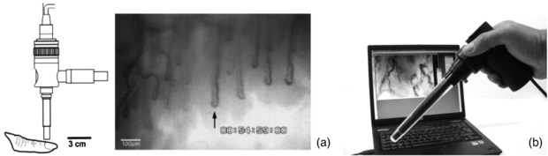
Figure 13. (a) Example capillary images from the nailfold region of the finger. (b) KK Technology Capiscope HVCS Handheld Video Capillaroscopy system. The NFC probe has an integral light source and allows images to be collected from the nailfold area, and also sublingually. (Courtesy of KK Technology.)
Download figure:
Standard image High-resolution imageNFC not only can help visualize the surface microvessels by microscopy, it can also be employed in combination with sophisticated methods in order to measure red blood cell velocity (figure 14), capillary pressure (i.e. cannulated capillaries using micropipettes and micropressure devices) (Morris et al 1996, Shore 2000) and transcapillary diffusion of a fluorescent tracer (sodium fluorescein injected intravenously—passage through vessels evaluated with a fluorescence microscope), thus allowing comprehensive physiological and pharmacological studies in humans (Bollinger and Fagrell 1990).
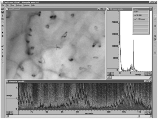
Figure 14. Skin capillaries from anterior aspect of wrist with KK Technology Capillary CAM1 anemometer system velocity recording at a single loop apex. Note the pulsatile component which is superimposed on low frequency vasomotor activity, www.kktechnology.com/cam1.html. (Courtesy of KK Technology.)
Download figure:
Standard image High-resolution image2.4.2. Clinical applications of capillaroscopy
The microcirculation has a fundamental role in the genesis of many autoimmune diseases including connective tissue disorders and diabetes. Before studying pathological changes, it is important to be able to identify normal capillary morphology and blood velocity patterns (Cutolo 2010). In healthy adults the capillaries usually maintain a constant overall morphology and so sequential follow-up can be applied to monitor for abnormalities. Children however can exhibit irregularity in their capillary morphology, and loop density has been shown to be lower than in adults. Adults of advancing age can progressively develop mild, non-specific morphological changes including tortuousity and micro-aneurysms (Dolezalova et al 2003).
Raynaud's phenomenon and connective tissue disease.
More than 10% of patients who attend a specialist centre with RP will eventually develop a scleroderma-spectrum connective tissue disease (Spencer-Green 1998). Along with the presence of specific autoantibodies, an abnormal NFC is a key risk-factor for the development of SSc in patients presenting with RP. SSc is a multi-organ disease characterized by tissue fibrosis and immune/microvascular abnormalities. The disease is very important to diagnose early so that it can be treated aggressively at an early stage (Cutolo et al 2008, 2010) (figure 15).
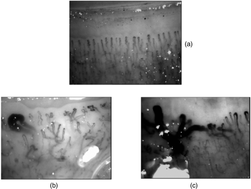
Figure 15. Example wide field capillaroscopy images from (a) a healthy subject and (b) and (c) significant microangiopathy in systemic sclerosis (SSc) with giant capillary structures and architectural disorganization clearly seen.
Download figure:
Standard image High-resolution imageThe presence of giant capillaries and micro-haemorrhages on NFC is sufficient to identify the 'early' scleroderma pattern, and an increase in these features along with the progressive loss of capillaries (active pattern) is followed by neo-angiogenesis, fibrosis and 'desertification' (late pattern) (Cutolo et al 2013). The sensitivity of the American College of Rheumatology's classification criteria for SSc increases from 67% to 99% with the addition of these specific NFC abnormalities. Telangiectasiae may form on the face and hands along with digital ulcers. Based on the appearance of the scleroderma pattern on NFC, almost 15% of patients progress from primary to secondary RP over a mean follow-up period of 29 ±10 months. Follow-up by NFC (every six months) is suggested for RP patients. A scoring system for NFC changes is available, and scores change significantly during follow-up of SSc patients (Cutolo et al 2013).
Several other NFC patterns have also been identified, with non-specific microangiopathy that can be seen in patients with Sjogren's syndrome (SS), systemic lupus erythematosus (SLE) and undifferentiated connective tissue disease (UCTD). Significant microangiopathy is also often evident in dermatomyositis. It is important to note that mild changes from the normal range can be seen in some patients with primary RP and acrocyanosis.
Diabetes.
Systematic vasculopathy is the most common complication of diabetes mellitus (DM) and much of its morbidity is attributable to the macrovascular and microvascular complications related to the degree of hyperglycaemia and hypertension. Changes are often seen in the retinal microvessel morphology in this patient group. Whilst capillary morphology has been assessed at the finger nailfold, there is uncertainty in its clinical diagnostic value. Reported changes in nailfold capillary morphology in DM include microaneurysms, apical dilatations, branching and haemorrhagic extravasations. However these features, with the exception of microaneurysms, can also be found in healthy subjects. A high frequency of dilatation at the apex of loops may be the key feature in diabetes, but these changes do not appear to be linked to disease duration or disease sub-type (Bollinger and Fagrell 1990, Fahrig et al 2000).
Some studies have investigated the link between skin and retinal blood vessel changes in diabetes, with the venous limb dilatation observed by ophthalmoscopy similar to the pathological changes seen by capillaroscopy. Abnormal leakage of sodium fluorescein has also been described in diabetes and this has been reported to appear earlier in the cutaneous capillary loop than in the retina (Chang et al 1997). Other authors however have found no such link between eye and finger abnormalities (Gasser and Berger 1992, Trapp et al 1986). By studying capillary recruitment and density, the skin microvascular reactivity in response to vasodilatatory l-arginine infusion has been shown to be impaired in patients with later onset of type 1 diabetes (Neubauer-Geryk et al 2013).
2.4.3. Other clinical applications
Non-specific microangiopathy at the nailfold site can also be identified in a variety of other conditions. Care needs to be taken in clinical capillaroscopy examinations to know a patient's wider health status when reporting on morphology. For example, Ribeiro et al (2012) showed that a group of 46 dermatology patients with psoriasis had a significantly lower capillary density, increased avascular areas and increased general morphological abnormalities compared to a group of 50 control subjects. However, no association was found between capillary density and the duration of the disease or the extent of skin involvement as measured by the psoriasis area and severity index (PASI) score. Furthermore, the presence of avascular areas was more common in psoriatic individuals whose nails were affected by the condition. NFC may also give valuable information about some features of patients with glaucoma. In a study by Park et al (2011) of 108 glaucoma patients, nail bed haemorrhage and loss of nailfold capillaries were strongly associated with the presence of optic disc haemorrhage. No differences were observed between patients with normal tension glaucoma and patients with primary open-angle glaucoma.
Skin ischemia is one of the crucial phenomena during chronic lower limb ischemia in patients with peripheral arterial occlusive disease and/or diabetes. However, risk stratification for development of ischemic ulceration and/or skin necrosis in those patients is not easy. Monitoring of microcirculatory parameters, as part of an integrated diagnostic approach, may have a considerable value in the evaluation of risk of progression of the disease and the effectiveness of therapeutic intervention in individual patients. Capillaroscopy has been used by many groups worldwide in relation to wound healing, including venous ulcer healing (Ambrózy et al 2013), critical limb ischaemia assessment (Kluz et al 2013), and its response to spinal cord electrical stimulation therapy (Colini Baldeschi and Carlizza 2011).
Capillaroscopy has also been applied to assessing endothelial function by measuring skin capillary density and recruitment and also red blood cell velocity changes with post-occlusive reactive hyperaemia (Cheng et al 2013). This approach has been reported in testing anti-hypertensive treatment (Kaiser et al 2013) where capillaroscopy was used to assess, in 44 hypertensive patients and 20 age- and sex-matched controls, if metoprolol succinate (a β1 -adrenoceptor blocker) or olmesartan medoxomil (an angiotensin II AT1-receptor blocker) reverses microvascular dysfunction in hypertensive patients. They found that capillary rarefaction and microvascular endothelial dysfunction in the patient group responded favourably to long-term pharmacological treatment.
3. Emerging imaging technologies in microvascular assessment
Building on the established optical imaging technologies described in the previous sections, there are numerous new approaches to obtaining information that describes the microvasculature, surrounding micro-structures and tissue perfusion in health and disease. This section looks at emerging technologies and describes a selection of exciting methods that are on the horizon for clinical application (Dunn et al 2011).
3.1. Imaging PPG
Photoplethysmography imaging (iPPG) is a non-contact imaging method for mapping cardiac synchronous pulsations i.e. perfusion across an area of tissue. iPPG has various forms and can be single wavelength field illumination (near infrared) or dual wavelength illumination (both red and near infrared). iPPG can also be used to determine oxygen saturation by employing algorithms and empirical formulae similar to that of traditional single site contact pulse oximetry. iPPG mapping of pulsatility represents the regional perfusion for the superficial blood vessels including the microcirculation. iPPG has capability for high resolution, fast scanning speeds and can ultimately be of low-cost. The technique can be unreliable where there is significant movement artefact, and correction algorithms are a key part of ongoing technology development. Currently, the literature on iPPG relates to technical advances rather than clinical utility and validity. One very important area with significant commercial potential is its translation to the very low-cost webcam platform. Examples of cardiac synchronous waveforms that can be obtained from the forehead site with iPPG are shown in figure 16.
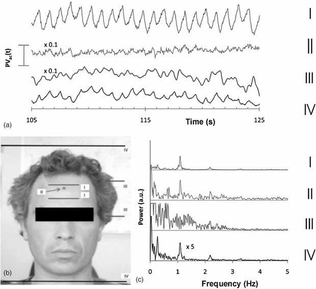
Figure 16. Cardiac pulsations at different digital camera colours measured from the forehead using iPPG from ambient lighting. Heart rate variability power spectra are also shown (permission granted to re-use from Verkruysse et al 2008 Opt. Express 16 21434–45).
Download figure:
Standard image High-resolution image3.1.1. Background
Traditional photoplethysmography (PPG) is a non-invasive contact optical method to detect the cardiovascular pulse wave, usually from the peripheral tissues (Allen 2007). The technology in its most basic form requires only two optoelectronic components: a light source to illuminate the tissue and a photodetector to measure small variations in light intensity arising from light interaction with the illuminated tissue. The origin of the changes in light intensity are not fully understood, although several mechanisms are thought to be involved including the shifting orientation of red blood cells between systole and diastole, vessel wall movement, and variations in tissue blood volume. PPG has been well reported in the literature and has a vast range of clinical applications including oxygen saturation (pulse oximetry), heart and respiration rates, blood pressure and cardiac output, assessment of autonomic function, and detection of peripheral vascular disease (Allen 2007). PPG is a tissue contact technique and is limited to a single or small number of measurement spots.
iPPG has been developed recently to give full-field and non-contact images of tissue pulsatility and perfusion. Measurement systems usually operate in reflection mode where both the illuminating light source and photodetector are situated alongside each other in dual or triple wavelength configurations. Typically, 660 nm and/or 880 nm ring illumination sources are used for dual wavelengths. Wieringa et al (2005) has described the development of SpO2 imaging technology based on three wavelengths: 660, 810 and 940 nm. Sun et al (2012) have described the use of ambient light in remote photoplethysmographic systems to assess the utility of low-cost webcams to detect the pulse from the skin.
The detector technology usually comprises a high sensitivity CMOS camera which is held at a fixed distance, e.g. 10–20 cm from the tissue, to measure the variations in light (typically 2–5% of overall reflected light). Images can be collected at rates of tens of frames per second (fps), enabling the pulsatile components to be extracted without aliasing. Image processing comprises various stages, including band-pass filtering and averaging of regions of interest (ROI). The time-varying intensity modulation is strongly affected by relative movement of the camera and body so image processing methods are used to reduce the effect of motion artefacts e.g. by averaging of pixels or Fourier analysis techniques (Wieringa et al 2005, Verkruysse et al 2008). Other centres have experimented with lock-in amplifiers to improve the signal-to-noise ratio (Kamshilin et al 2011). The sensitivity of modern systems allows measurements to be made using very low cost webcams and distances from camera to measurement surface can now typically be 1 m (Rubins et al 2011) (figure 17).
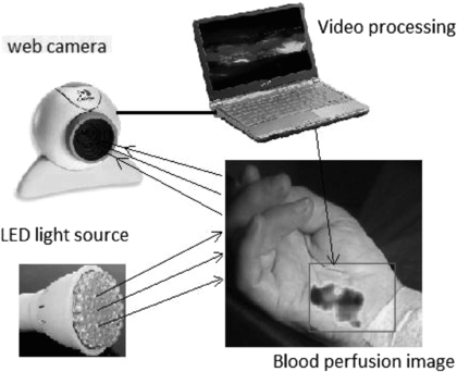
Figure 17. iPPG system comprising light source (4 W bulb of 80 white LEDs) and standard web camera with image processing performed on a laptop computer. The system can acquire images at 15 fps with resolution 640×480 to calculate blood perfusion changes in real-time (permission granted to re-use from Rubins et al 2011 IFMBE Proceedings vol 34 (Berlin: Springer) pp 183–6).
Download figure:
Standard image High-resolution imageEarly iPPG imaging systems were limited by low frame sampling rates, restricting their clinical use, for example in the assessment of pulse rate and its variability. Developments have been promising in terms of speed and sensitivity. The key physiological parameters i.e. respiration rate, heart and also pulse rate variability (PRV) derived from the iPPG datasets can yield statistically comparable results to those acquired using a contact PPG sensor (Sun et al 2013). Advanced physiological monitoring has been reported by Hu et al (2009, 2010) using opto-physiological modelling to extract information on superficial and deeper tissue blood volume perfusion levels (figure 18).
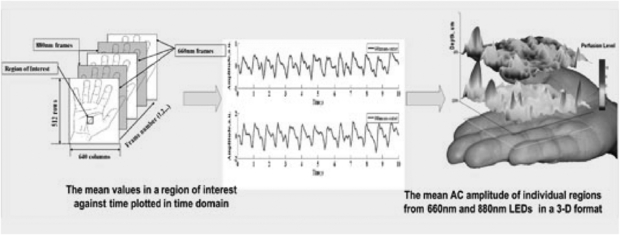
Figure 18. Cardiac synchronous pulses from a dual wavelength iPPG system for a region of interest on the hand. The 2D pulsatility can be seen. Image processing at two wavelengths with opto-physiological modelling enables a 3D representation for two tissue depths; superficial and deep. (Courtesy of Professor S Hu, Loughborough University.)
Download figure:
Standard image High-resolution image3.1.2. Applications, validation and comparison with other microvascular measurement techniques
iPPG technology development has advanced in the last few years, but with few clinical validation papers published in the literature. Early validation has been mainly in healthy controls and has included monitoring simple vascular responses using scratching of the skin (Kamshilin et al 2011), reactive hyperaemia following removal of a temporary vascular occlusion (Kamshilin et al 2013), and measurements made during exercise (Sun et al 2011).
Wieringa et al 2005 described the development of a method for imaging the arterial oxygen saturation (SpO2) distribution within tissue. They used a three wavelength system with a monochrome CMOS camera, an apochromatic lens and a three lambda-LED ring light (i.e. 660, 810 and 940 nm) and compared images with respiration and ECG (heart rate) measurements in seven volunteers. Movies were processed by dividing each image frame into discrete ROI, averaging 10 × 10 raw pixels each. For each ROI, pulsatile variation over time was assigned to a matrix of ROI-pixel time traces with individual Fourier spectra. Images derived from photoplethysmograms correlated well with respiration reference traces at the three wavelengths. This early feasibility study also showed the potential for non-contact 2D imaging reflection-mode pulse oximetry.
Rubins et al (2011) evaluated the reliability of a high resolution webcam based single wavelength system by comparing its measurements with LDPI at the palmar surface of the hand during local warming. Results showed that the amplitude of the iPPG increased immediately after warming and had good correlation with the mean LDPI perfusion (correlation 0.92, p <0.0001), giving confidence that the iPPG technique has good potential for the non-contact monitoring of blood perfusion changes.
Sun and co-workers (2011) assessed the performance of an iPPG system by measuring the cardiac pulse from images of the hand in 12 subjects before and after 5 min of cycling exercise. A new motion artefact reduction method was implemented based on planar motion compensation and blind source separation. The physiological parameters (i.e., heart rate, respiration rate) derived from the images captured by the iPPG system exhibited functional characteristics comparable to conventional contact PPG sensors. Such continuous recordings from iPPG reveal that it is possible for heart and respiration rates to be successfully tracked in high-intensity physical exercise situations. Although monitoring pulse rate has been shown to be feasible by iPPG, the precise measurement of heart rate variability is challenging. Sun et al (2013) also described a system capturing iPPG images at 200 fps. An important outcome was that the negative influence of a low sample frequency can be compensated via interpolation to improve the time domain resolution. This work therefore showed the potential of low-cost webcam-based iPPG for the evaluation of cardiac and peripheral autonomic activity.
Kamshilin et al (2013) demonstrated a novel method of iPPG image processing for tracking blood flow changes in skin before, during and after arm occlusion. They showed the extensive variability in the 2D distribution of blood pulsation between cardiac cycles and spatially, as would have been seen if measured using another established microvascular perfusion imaging technique such as LDPI.
3.2. Optical coherence tomography
Optical coherence tomography (OCT) is an imaging method that can be applied for the evaluation of sub-surface tissue morphology, giving a spatial resolution (typically 5 to 10 µm) significantly higher than other established imaging techniques such as MRI or ultrasound (Fujimoto et al 2000). OCT is analogous to ultrasound imaging; it uses infrared light instead of sound to provide imaging information in tissue typically of 1 to 3 mm in depth. No ultrasound gel needs to be applied to the tissue as long as the OCT probe is in contact with the tissue surface.
OCT can function as a type of optical biopsy, and is a powerful imaging technology for medical diagnostics providing cross-sectional images of tissue structure on a micron scale in situ and in real-time. The technology has a wide range of clinical applications, including microvascular network visualization (Mahmud et al 2013), dermatology (Gambichler et al 2005), histology (Jung and Boppart 2013, Kuck et al 2014, Qi et al 2010), dentistry e.g. oral structural and vascular imaging (Davoudi et al 2012, Tsai et al 2013), cardiology e.g. coronary artery visualization (Nammas et al 2013, Tearney et al 2012) and ophthalmology (Hahn et al 2011, Willerslev et al 2013).
3.2.1. Background
The technique employs a low power laser, usually infrared, shone onto tissue. Boundaries between the tissues reflect back a small amount of light, and this reflected signal is detected and processed. Image construction arises primarily from the refractive index variations at these tissue discontinuities and micro-structures. OCT with a near infrared light source can give information about the epidermis-dermis junction in skin.
OCT is based on interferometry i.e. the interference between reflected light and a reference beam, which is used as a coherence gate to isolate light from specific depths. A Michelson interferometer is often used to perform the low-coherence interferometry for OCT (Fujimoto et al 2000). The frame rate for early OCT systems was typically 4 to 8 fps but faster modern systems are available at beyond video frame rate (depending on imaging parameters). A schematic representation of an OCT system is shown in figure 19 and example OCT B-mode image in figure 20.
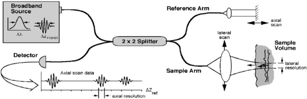
Figure 19. Schematic of a time domain OCT instrument based on a fibre optic implementation of a Michelson interferometer. One arm of the interferometer is interfaced to the measurement instrument and the other arm has a scanning delay line. Reflections or backscattering from the object being imaged are correlated with light which travels the reference path. The envelope of the interference fringe signals yields the depth profile for the sample. In contrast, the interference fringe signals associated with the Fourier domain OCT are detected as a function of optical frequency (from Fujimoto et al 2000). These components can be miniaturized for adaptation to endoscopes or mounting in microscopes. (Permission to re-use granted by Thorlabs Ltd.)
Download figure:
Standard image High-resolution image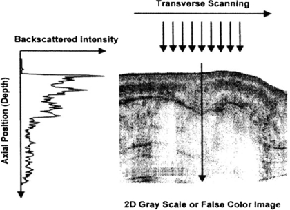
Figure 20. Example OCT B-mode scan of tissue formed from a sequence of axial line (A-) scans. Cross-sectional images are constructed by performing measurements of the echo time delay of light at different transverse positions. The result is a two-dimensional data set which represents the backscattering in a cross-sectional plane of the tissue. This data can be displayed as a grayscale or false colour image (permission granted to re-use from Fujimoto et al 2000 Neoplasia 2 9–25, copyright Elsevier). A sequential series of these B-mode images across the tissue can be combined to form a 3D image.
Download figure:
Standard image High-resolution imageThere are various OCT systems available. Michelson Diagnostics (Orpington, Kent UK) is an established manufacturer of clinical OCT technology. Their 'VivoSight' optical OCT probe comprises four parallel swept source OCT systems using a laser with central wavelength of 1310 nm and with a 150 nm sweep. It can be configured to automatically capture 'N' brightness (B-) mode scans with a set interspacing to produce a 3D re-construction of the tissue, a typical image size obtained being 4 × 0.4 × 2 mm. Axial (A-) line scanning information is also available.
Second-generation OCT systems, known as Fourier (frequency) domain OCT, are now available including the Thorlabs Spectral Radar OCT imaging system (Newton, NJ, USA). Frequency domain techniques have several advantages over time domain systems including a higher sensitivity and speed. The improved speed allows for rapid cross sectional image collection, enabling facile imaging of larger sample volumes in real-time. Additional contrast mechanisms are able to extend the capability of OCT. Doppler OCT or optical Doppler tomography is one kind of functional extension of OCT which combines the Doppler principle with OCT and provides in-vivo functional imaging of moving samples, flows and moving constituents in biological tissues (Liu 2012) (figure 21).
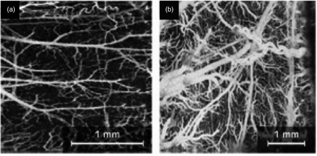
Figure 21. Doppler OCT imaging: (a) microvasculature of a mouse cerebral cortex and (b) microvasculature of a rat cerebral cortex. Scale bars are shown (permission granted to re-use from Liu and Chen 2013 Chin Opt. Lett. 11 011702).
Download figure:
Standard image High-resolution imageThe selection of wavelength for a particular OCT system depends on specific application requirements. Image quality depends both on the type of sample, as well as system design. For example, water is more transparent to light in the 600–900 nm wavelength range. Since the outer portion of the eye (cornea, vitreous humour and lens) is mostly water, OCT imaging at 800 nm has become the industry standard in many ophthalmic applications. For multi-layered biological tissue (skin, brain, GI tract, etc) the 900–1400 nm range is appropriate, since longer wavelengths typically provide better penetration depth.
In general, the resolution depends on the coherence length of the light source. Shorter coherence lengths, which are associated with broader spectral bandwidths and shorter wavelengths, lead to better axial (longitudinal) image resolution. For most OCT applications the axial resolution is approximately 10 µm. With a measurement depth of the order of 1 mm this should allow imaging of the stratum corneum, the epidermis with the basal membrane zone, and the structures of the upper dermis (which consists of fibroblasts embedded in a network of collagen fibres and small blood vessels).
3.2.2. Applications, validation and comparison with other microvascular measurement techniques
Although OCT is becoming established in specific clinical specialties including ophthalmology (Hahn et al 2011), histology (Jung and Boppart 2013), dentistry and human oral cavity imaging (Davoudi et al 2012), and cardiology, its application appears focussed to the study of the microstructures associated with the small blood vessels rather than specifically the blood vessels per se.
Cardiology OCT has been used in coronary artery assessment (Nammas et al 2013) giving a near tenfold improvement in resolution over intravascular ultrasound. Valuable information was extracted for the in vivo study of vascular scaffolds in stents around a coronary artery, and vessel wall injuries such as dissection, thrombosis and tissue protrusion. Of course, coronary arteries are significantly larger than the capillary vessels but the studies show the potential for studying microangiopathy. A review of OCT applications in dermatology by Gambichler et al (2005) showed the potential for 'histological' assessment of the superficial skin layers, skin appendages, blood vessels, cutaneous inflammation, hyperkeratotic conditions and photoadaptive responses.
An example OCT image of the nailfold skin in a patient with SSc is shown in figure 22. The cross-sectional view indicates the region of dilated blood vessels. This imaging shows the fine static detail of the tissues and a further advancement of the technique would be to superimpose Doppler OCT blood flow information onto the image (Mason et al 2004).
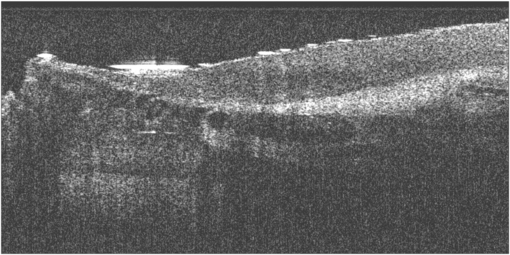
Figure 22. Example OCT B-mode scan giving a cross-section of the finger nailfold region in a patient with systemic sclerosis (SSc). The nailfold region is to the upper left hand part of the image, with the darkest circular regions indicate the dilated capillary region. Skin thickness assessments have also been described in Abignano et al (2013).
Download figure:
Standard image High-resolution imageDoppler OCT holds great promise for ophthalmology applications. Willerslev et al (2013) used spectral domain OCT and showed that the direction of blood flow at dichotomous vascular branchings can be determined. This feature may assist in the identification of flow reversal near sites of vascular occlusion. They also analysed blood flow near vascular malformations. Kagemann et al (2009) used a spectral domain OCT system to study a glass capillary tube of sub-millimetre diameter perfused with milk. They calculated the Doppler shifts from temporal changes in phase and showed that the observed percentages of the velocity profile at or below the Nyquist frequency was highly correlated with the predicted percentages. Cito et al (2012) successfully tested spectral domain OCT methods in various liquids passing through the microchannels of micro-fluidic devices.
An overview of the applications for OCT in imaging microvascular networks was given by Mahmud et al (2013) who described its potential roles for assessing retinal and choroidal vasculature, cardiac vasculature, central nervous system, and tumour models. They compared two general classes of microvascular imaging techniques and their algorithms: speckle-variance and phase-variance OCT.
Fujimoto and Drexler (2008) also review OCT technology and describe its use in imaging ocular blood flow, mapping cortical haemodynamics for brain research, drug screening, monitoring changes in image tissue morphology and haemodynamics following pharmacological intervention and photodynamic therapy, evaluating the efficacy of laser treatment in PWS patients, assessing the depth of burn wounds, imaging tumour microenvironment, and quantifying cerebral blood flow.
3.3. Photoacoustic tomography
Photoacoustic (or optoacoustic) tomography (PT) is an umbrella term for a range of imaging methods that can provide detailed images of tissue types and blood oxygenation levels. PT can image blood vessels in highly scattering tissue and can discriminate between arteries and veins (Kruger et al 1995). An excellent review of the technology is given by Beard (2011).
PT combines optical absorption contrast and highly scalable spatial resolution i.e. from micrometer optical resolution to millimetre acoustic resolution. PT has three main embodiments: microscopy, computed tomography, and endoscopy (Hu and Wang 2010a, 2010b) with representative applications in microvascular-related physiological and pathophysiological research, including haemodynamic monitoring, chronic imaging, tumour–vascular interaction (Ehling et al 2013), neurovascular coupling (Hu and Wang 2010a), and drug discovery biomarkers (Bednar and Ntziachristos 2012).
3.3.1. Background
PT involves shining a very short light pulse (typically a few tens of ns width) onto tissue via an optical fibre. Wherever this light is absorbed, the energy from the light warms that region of tissue or blood, in the region of one thousandth of a degree Kelvin. This warming causes the absorbing region to expand rapidly by a very small amount, with this thermoelastic expansion causing a pressure wave to be set up which travels through the tissue at the speed of sound, before being picked up by a high frequency (e.g. 30–70 MHz) focussed ultrasound detector. The more a section of tissue or region of blood absorbs, the hotter it becomes and the greater the ultrasound signal it creates. So unlike a standard ultrasound image, the photoacoustic image reveals the different optical absorption properties of tissue or blood (figure 23). As with diffuse optical tomography different wavelengths of light, for example green and infrared, are used to reveal varying levels of oxygenation in the blood as well as different tissue types (extract from 'IPEM Spotlight on Optical techniques in Medical Imaging', 2006).
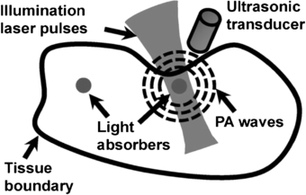
Figure 23. Photoacoustic tomography imaging method (permission granted to re-use from Yao and Wang 2011 Contrast Media Mol. Imaging 6 332–45). Photoacoustic signals are induced by pulsed laser illumination. When laser energy is absorbed by biological tissues, the resulting very minimal heating of the tissues generates ultrasonic waves. The waves can be detected by a transducer and then used to create an image of the optical absorption distribution inside the tissues. Different soft tissue types in the body differentially absorb laser light of different wavelengths, providing high inherent contrast.
Download figure:
Standard image High-resolution imageThe technique can provide 3D images with significant depth of penetration up to 7 cm. The image resolution is in the order of 10–100 µm. Image acquisition time can be of the order of tens of minutes. PT imaging has the important advantage that the photoacoustic signals can be detected on the same side and over the same region of tissue that is irradiated with the excitation light (figure 24). This is particularly important for imaging skin and superficial blood vessels (figure 25).
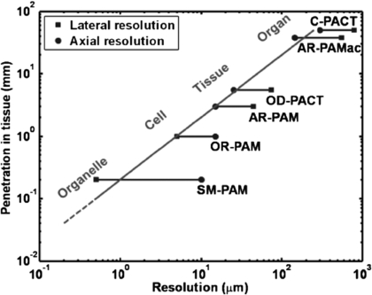
Figure 24. Spatial resolution versus penetration depth in multi-scale PT (summary reproduced with permission from Hu and Wang 2010a Front. Neuroenerg. 2 10). SM-PAM: sub-micron photoacoustic microscopy; OR-PAM: optical-resolution photoacoustic microscopy; AR-PAM: acoustic-resolution photoacoustic microscopy; OD-PACT: optical-detection-based photoacoustic computed tomography; AR-PAMac: acoustic-resolution photoacoustic macroscopy; C-PACT: circular photoacoustic computed tomography.
Download figure:
Standard image High-resolution image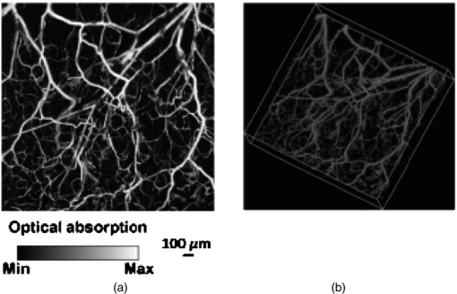
Figure 25. Photoacoustic tomography (PT) example images of mouse model microvasculature from head measurements (permission granted to re-use from Hu and Wang 2010b J. Biomed. Opt. 15 011101), giving time resolved ultrasonic detection of (a) maximum amplitude projection image and (b) 3D morphology.
Download figure:
Standard image High-resolution image3.3.2. Applications, validation and comparison with other microvascular measurement techniques
Wang (2008) summarized the great potential for the technology, including melanoma detection, endoscopy, molecular imaging, gene expression, Doppler PT for flow measurement, metabolic rate measurements, mapping of sentinel lymph nodes, and breast and brain imaging. PT can be combined with other imaging modalities, including OCT, to enhance the information derived in microscopy (Li et al 2009), and also endoscopy. (Xi et al 2013). Xiang et al (2013) have advanced the 3D imaging and developed a 4D PT technique that generates motion pictures of imaged tissue, enabling real-time tracking of dynamic physiological and pathological processes at hundred micrometer-millisecond resolutions. The 4D PT technique was used to image needle-based drug delivery and study pharmacokinetics. It has also been suggested as a technique to monitor the fast haemodynamic changes during interictal periods in epilepsy and also the temperature variations during tumour thermal therapy.
Specific clinical studies include the identification of inflammatory arthritis and also breast cancer. Rajian et al (2012) used PT to identify neovascularity (angiogenesis) which is an early feature of inflammatory arthritis, thus giving an early diagnosis and facilitating treatment monitoring of the disease. A rat model was tested with imaging at two different wavelengths, 1064 and 532 nm, to reveal that there is a significant signal enhancement in the ankle joints of arthritis-affected rats when compared to a normal control group. Histology images obtained from both the normal and the arthritis-affected rats correlated well with the PT findings, supporting the view that PT could become a new tool for clinical management of inflammatory arthritis.
Manohar et al (2005, 2007) explored the utility of PT in breast cancer patients. Near-infrared photoacoustic images (figure 26) of ROI in four of the five cases of patients with symptomatic breasts revealed higher intensity regions attributed to vascular distribution associated with cancer. Of the two cases presented, one was especially significant, with benign indicators dominating in conventional radiological images, while photoacoustic images revealed vascular features suggestive of malignancy, corroborated by histopathology. The results showed that PT may have potential in visualizing certain breast cancers based on intrinsic optical absorption contrast. A future role for the approach could be in supplementing conventional breast imaging to assist detection and/or diagnosis. Improvements in contrast have been shown in a mouse tumour model by combining high-resolution near-infrared light-induced PT with NIR dye-labelled amino-terminal fragments of urokinase plasminogen activator receptor (uPAR) targeted magnetic iron oxide nanoparticles (NIR830-ATF-IONP) (Xi et al 2014). The accumulation of the targeted nanoparticles in the tumour led to photoacoustic contrast enhancement due to the high absorption of iron oxide nanoparticles (IONP). Near infrared fluorescence images were used to validate specific delivery of NIR830-ATF-IONP to mouse mammary tumours. Systemic delivery of the targeted IONP to the tumours produced a four-fold enhancement in photoacoustic signals compared to tumours that received non-targeted IONP. The use of targeted nanoparticles allowed imaging of tumours located deeper than 3 cm beneath healthy tissues. The study indicated that the combination of PT and receptor-targeted NIR830-ATF-IONP can provide improved specificity and sensitivity for breast cancer detection.
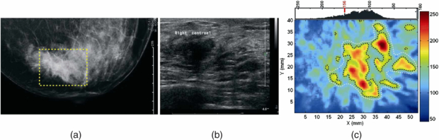
Figure 26. Invasive ductal carcinoma in the breast. (a) X-ray mammogram reveals abnormalities in architecture, (b) transverse sonographic scan image shows 17 mm irregular hypo-echoic solid mass, and (c) photoacoustic image reveals higher intensity regions attributed to tumour vascularization. Breast image obtained using 1064 nm laser excitation and ultrasound frequency of 1 MHz to give an imaging depth of approximately 2 cm and resolution of 2 mm. Image acquisition time was ∼30 min (permission granted to re-use from Manohar et al 2007 Opt. Express 15 12277–85).
Download figure:
Standard image High-resolution image3.4. Hyperspectral imaging
Hyperspectral imaging (HSI) is a new optical imaging method that can map tissue e.g. oxygen saturation levels, for example to study microvascular perfusion in skin (Lua and Fei 2014). HSI is a spectroscopy technique originally developed for military and geological remote sensing applications giving distinct spectroscopic 'fingerprints' for different molecules. More recently there has been interest in developing aspects of the technology for biomedical applications, e.g. the detection and segmentation of cancer and the measurement of tissue oxygenation relating to haemoglobin in perfused tissues (Sorg et al 2005, Kiyotoki et al 2013). Other applications of HSI include sickle cell disease (Zuzak et al 2003), ophthalmology (Patel et al 2013), diabetes (Nouvong et al 2009), and wound healing (Jafari-Saraf et al 2012).
3.4.1. Background
HSI is based on a spectroscopic technique and involves the generation of a 'hyperspectral' cube stack of spatial and spectral information. This '3D' data cube set comprises, at each pixel of the image, a full spectrum. The spectra generated would depend on both target illumination and detector characteristics. In practice, the field of view is externally illuminated with a broad spectrum light source, with uniform 'white light' illumination across the visible wavelengths (400–700 nm). The illumination can also extend to near infrared depending on what tissue is being studied.
A key medical application of HSI is the spatial non-invasive measurement of tissue oxygen saturation (SO2). Although there are spot measurement devices commercially available that can measure SO2 in skin, these are contact based and localized. The contact pressure can add to the uncertainty in the values measured. Furthermore, there are clinical applications where sterile non-contact methods are required such as in burns assessment and wound healing. HSI can calculate SO2 from established methods by comparing absorption spectra in the green part of the spectrum where high oxygen saturation in tissue haemoglobin has a pulsatile spectrum whereas reduced haemoglobin is monophasic and damped (figure 27).
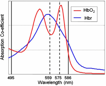
Figure 27. Tissue oxygen saturation levels can be obtained using wavelengths in the green wavelength range. Haemoglobin that has high levels of tissue oxygen saturation (HbO2) has a pulsatile spectral response whereas reduced haemoglobin (Hbr) has damped spectra. Interpolation techniques can be applied from absorption spectra at key wavelengths to give a measure of tissue oxygen saturation (SO2).
Download figure:
Standard image High-resolution imageA key advancement in HSI technology is the development of narrow band tuneable filters which have the characteristic ability to transmit electromagnetic radiation through a very narrow bandpass of spectral region over a wide spectral range (Yuen and Richardson 2010). Filter types include acousto-optical filters and liquid crystal tuneable filters, with each having specific advantages and disadvantages (Gat 2000). Challenges still remain with HSI development in dealing with mixed spectra and also the scattering effects in biological tissues.
3.4.2. Applications, validation and comparison with other microvascular measurement techniques
There are many potential applications for HSI in assessing the microcirculation and associated perfusion, but the literature is currently limited and there are few clinical studies reported on the human microcirculation. Example HSI images are shown for SO2 mapping in forearm skin sensitivity testing (figure 28) and in diabetic foot ulcer assessment (figure 29).
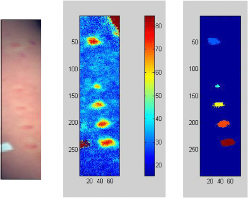
Figure 28. Tissue oxygen map of skin for different doses of sodium urate (the 'urate skin test') in a healthy volunteer. The skin inflammation reaches an oxygen saturation level close to 80% (permission granted to re-use from Rodmell 2005 PhD thesis University of Nottingham, UK).
Download figure:
Standard image High-resolution image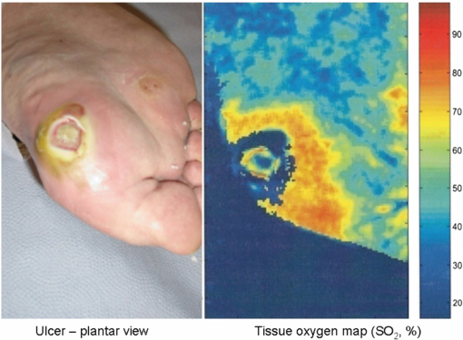
Figure 29. Tissue oxygen map of skin at and surrounding a foot ulcer in a diabetic patient. The complex spatial variation in SO2 can be seen. (With permission to re-use from Professor W Jeffcoate, Nottingham University Hospitals Trust.)
Download figure:
Standard image High-resolution imageNishino et al (2013) developed a method for the assessment of allergic dermatitis by using the long-wavelength near-infrared spectrum to detect intracutaneous allergic type-specific elements. A spectral canonical discriminant analysis (CDA) classifier was established for the spectra of type I and type IV allergic dermatitis reactions and achieved accurate detections by good specificity and sensitivities overall, suggesting a possible application of near-infrared spectral imaging to the assessment of allergic dermatitis.
Foot ulceration remains a major health problem for diabetic patients and has a major impact on the cost of diabetes treatment. HSI has great potential to quantify cutaneous tissue haemoglobin oxygenation in this group from generated anatomically-relevant tissue oxygenation maps to assess the healing potential of diabetic foot ulcers (figure 29).
Yudovsky et al (2011) developed an HSI algorithm based on an experimentally validated skin optical model and inverse algorithm to monitor temporal changes in epidermal thickness and oxyhaemoglobin concentration in diabetic feet at pre-ulcerative sites. They pilot tested this in a few patients. The algorithm was also able to observe reduction in the epidermal thickness combined with an increase in oxyhaemoglobin concentration around the ulcer as it healed and closed, showing potential for the methodology to be used for the early prediction of diabetic foot ulceration in a clinical setting.
Nouvong et al (2009) reported a larger study of a prospective single-arm blinded design in 66 patients with type 1 and 2 diabetes and followed over a 24 week period. Transcutaneous oxygen tension (tcPO2) was measured at the ankles as a reference. Superficial tissue oxy-haemoglobin (oxy) and de-oxyhaemoglobin (deoxy) were measured with HSI from intact tissue bordering the ulcer and a healing index derived from oxy and deoxy values for assessing the healing potential. A total of 73 ulcers were studied in total, of which 19 did not heal. The sensitivity for the healing index was 80%, specificity 74%, and positive predictive value 90%. The results indicated that cutaneous tissue oxygenation correlates with wound healing in diabetic patients. They concluded that HSI of tissue oxy and deoxy may predict the healing of diabetic foot ulcers with high sensitivity and specificity based on information obtained from a single visit.
Ophthalmology and the study of the retinal blood vessels is another important area of opportunity for HSI. In a study by Shahidi et al (2013) they used an HSI system to investigate regional differences in oxygen saturation of blood in first degree retinal vessels using a novel non-flash hyperspectral retinal camera in nine healthy individuals. Specific images were collected at 548, 569, 586, 600, 605 and 610 nm. Optical density values were extracted with the aid of Image-J software for blood oxygen saturation (SO2) determination. Arteriolar and venular SO2 were measured at three locations (ranging 1–3 optic nerve head radii) from the disc margin along the vessels in the superior and inferior temporal quadrants. They found greater SO2 values in the superior temporal first degree retinal arterioles and venules in young healthy individuals than in the equivalent inferior vessels. However, there were no detectable differences in retinal SO2 along each of the major vessels, a finding that is consistent with the concept of these vessels not contributing primarily to gas exchange. Moreover, SO2 was consistently higher in the arterioles than in the equivalent venules (p < 0.0001).
3.5. Tissue viability imaging
Tissue viability imaging (TiVi) is a new microvascular imaging method for the evaluation of red blood cell concentration in skin. The technique confers no information about erythrocyte velocities, and is thus not a measure of microvascular perfusion per se. A number of studies have nonetheless investigated the relationship between TiVi and more established techniques for the assessment of perfusion (in particular laser Doppler flowmetry). TiVi provides a low cost, rapid, full-field image of red blood cell concentration at high resolution that is not susceptible to the movement artefact that limits the laser-based blood perfusion techniques.
3.5.1. Background
The optical properties of red blood cells in the reticular dermis are highly dependent on wavelength, with strong absorption at green wavelengths, but only weak absorption of red spectral components. Absorption by the static tissue in the dermis is, in contrast, almost invariant across the visible light waveband. Spectroscopic evaluation of the proportional absorption of red and green wavelengths from skin, flash-illuminated by a xenon lamp, thus allows an estimation of red blood cell concentration within the tissue.
To ensure the light detected by TiVi originates from the reticular dermis, a cross-polarization technique is employed to filter the light reflected from the epidermis. Linearly-polarized light incident on skin will be partly reflected by the epidermal surface, mostly retaining its polarization in the process. Another portion of the incident light will instead undergo multiple scattering events in the reticular dermis and become depolarized. Figure 30 shows the configuration of a TiVi imager. A polarizing filter is placed over the xenon light source, and a second orthogonal polarizer is positioned over the detector to reject the light reflected directly from the skin surface. Depolarized light scattered within the reticular dermis is passed to the detector.
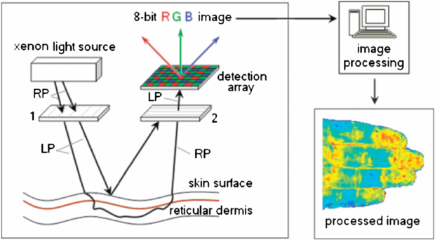
Figure 30. Light paths of randomly polarized (RP) and linearly polarized (LP) light in TiVi imaging of red blood cell concentration in the reticular dermis (permission granted to re-use from O'Doherty et al 2007 Skin. Res. Technol. 13 472–84).
Download figure:
Standard image High-resolution image
O'Doherty et al (2007) derived an algorithm for calculating a TiViindex representative of red blood cell concentration in the reticular dermis within the physiological range (0–4% RBC fraction of tissue volume), which accounts for light absorption in the epidermis and is almost independent of incident light intensity and oxygen saturation within the physiological range of 70 – 100% O2 saturation. McNamara et al (2010) express this algorithm in terms of a 1024 × 768 pixel TiVi output image matrix Mout, whereby:

Mred and Mgreen are the red and green colour planes of the image respectively, and p is a factor adjusted to derive the best linear fit between Mout and red blood cell concentration. Monte Carlo modelling suggests a measurement depth for TiVi of around 400–500 µm in skin with typical optical properties i.e. well within the reticular dermis.
3.5.2. Applications, validation and comparison with other microvascular measurement techniques
O'Doherty et al (2011) validated a high-speed TiVi system using an experimental model with red food dye pumped through tubing at pulsation rates similar to the cardiac cycle. Analysis of the images generated a power spectrum, with the peak power corresponding to the pumping frequency, along with harmonics. When the system was used to image red blood cell concentration at the human forearm and finger nailfold, peaks in the power spectral density were detected corresponding to the heart rate, plus a component attributed to vasomotion at 0.1 Hz.
Nilsson et al (2009) assessed the reproducibility and stability across four TiVi imagers when measuring from a plane surface of uniform colour. The maximum drift in output observed in any of the imagers on repeated measurements was only 1.02%. The mean TiVi output for all four imagers was also calculated, and the largest deviation from this mean observed in any individual device was found to be 4.14%. Dependence on image distance and size, and the influence of ambient lighting levels and surface curvature were evaluated. These factors did not unduly influence imager output provided highly curved surfaces were avoided.
O'Doherty et al (2009) compared TiVi, laser speckle contrast and laser Doppler line scanning instruments in measuring skin responses to the application of methylnicotinate (a vasodilator), a vasoconstricting corticosteroid, and forearm occlusion. TiVi exhibited a different response from the laser-based imaging techniques because of its sensitivity to red blood cell concentration rather than perfusion. The TiVi signal increased with forearm occlusion at 90 mmHg due to pooling of erythrocytes in the skin, but the effect was less pronounced with occlusion at 130 mmHg due to the rapid cessation of arterial inflow. TiVi was able to detect the vasoconstrictive effect of the topical corticosteroid, whereas the laser Doppler and speckle contrast devices were insensitive to vasoconstriction. TiVi and LSCI provided less deep measurements than the laser Doppler instrument, which could not detect the vasodilatation caused by methylnicotinate in the superficial skin. Petersen et al (2010) have also reported the evidence that TiVi may be more sensitive to vasoconstrictive pharmacological stimuli than laser Doppler methods, whereas the laser-based techniques may be more suited than TiVi for recording drug-induced vasodilatation.
Farnebo et al (2010) found a strong correlation between red blood cell concentration as measured by TiVi and laser Doppler perfusion measurements in assessment of post occlusive reactive hyperaemia at the forearm. The maximum responses and recovery times were found to be more reproducible when assessed by TiVi than by laser Doppler, probably because TiVi allows an evaluation averaged across an entire region of interest in the image, whereas laser Doppler data arises from a single point on the skin surface.
Zhai et al (2009) compared TiVi with colorimetry for the assessment of corticosteroid-induced skin blanching. They found that the two techniques had similar relative uncertainties, but the TiVi technique was not subject to the operator-dependent factors encountered in colorimetry such as variability in applied probe pressure or angle. TiVi was also able to detect blanching in cases of paradoxical skin erythema after corticosteroid administration.
4. Clinical outlook and summary for microvascular imaging techniques
The growing interest in the microvasculature has driven rapid and important developments in imaging methods for perfusion in microvessels. The non-invasive technologies are largely optical based to give the spatial resolution required and with specific wavelengths in the visible (green and red) and near infrared enabling perfusion to be determined within the microvascular bed. Table 1 summarizes key aspects of each of the nine imaging technologies and readers can look closer at the literature for each to determine the details, and also lack of evidence base, for the relevant clinical applications.
Table 1. Overview of typical characteristics for the microvascular imaging modalities described in this review.
| Wavelength (s) | Frame rate (fps) | Max. image dimensions | Operating principle | Examples of key clinical applications | |
|---|---|---|---|---|---|
| LDPI | Red (633 nm), or | <1 | ∼50 cm × 50 cm | Laser Doppler RBCs | Burn wound depth; endothelial |
| NIR (785 nm) | function testing | ||||
| LSCI | NIR (785 nm) | Up to 100 | ∼15 cm × 20 cm | Laser speckle contrast | Perfusion-superficial nutritive |
| RBCs | microvessels | ||||
| NFC | Green (for B&W imaging) | Video (e.g. 25) | ∼3 mm × 2 mm (typical | RBC light absorption, | Connective tissue disease |
| White (for colour imaging) | for widefield NFC) | cold light epi-illumination | diagnostics | ||
| TI | Typically | Up to ∼60 k | Whole body | Map of temperature | Thermoregulatory perfusion in the |
| 7–14 µm | with windowing | distribution using thermal IR | periphery; inflammatory responses | ||
| iPPG | NIR and red | Up to 200 | Whole body | Tissue pulsatility by | Heart rate variability; tissue |
| non-contact PPG | oxygenation saturation mapping | ||||
| OCT | NIR range | At least | <1 cm × 1–3 mm | Interferometry | Microvascular structure visualization; |
| (e.g. 800–1310 nm) | video rate | depth (typical) | histology; ophthalmology | ||
| PT | NIR or green | 10s possible | Depth, 10s of cm | Reconstruction of | Molecular imaging; melanoma |
| possible | photoacoustic source | detection; breast and brain imaging | |||
| distribution | |||||
| HSI | 200–25 000 nm | 100s possible | 10s of | Spectroscopy | Tissue oxygenation mapping; shock; |
| cm possible | cancer | ||||
| TiVi | 500–700 nm | Up to 50 | Whole body | Proportional absorption | RBC concentration in superficial |
| of red and green light | microvessels; studies of | ||||
| by skin | vasoconstriction |
LDPI—laser Doppler perfusion imaging; NIR—near infrared; LSCI—laser speckle contrast imaging; NFC—nailfold capillaroscopy; TI—thermal imaging (thermography); iPPG—imaging photoplethysmography; OCT—optical coherence tomography; PT—photoacoustic tomography; HSI—hyperspectral imaging; TiVi—tissue viability imaging; IR—infrared; RBC—red blood cell; fps—frames per second.
LDPI is now a firmly-established technique, with proven clinical utility in the field of burn-depth assessment, and a variety of devices now commercially available. For other clinical applications LDPI remains primarily used only in specialist clinical centres and research units. As the technology develops faster scanning and whole-field imaging, the expected improvements in performance could help LDPI achieve wider adoption. The full-field scanning LDPI systems are relatively new to the market, and so much of the evidence base for clinical applications lies with the raster line scanning systems.
In tandem with these developments, interest in the laser-speckle contrast method has encouraged a number of laser-Doppler manufacturers to enter the market with LSCI devices. Since LSCI provides a very superficial measurement in tissue, it may not be suitable for all applications. Nonetheless, rapid imaging rates across clinically-useful fields of view confer major benefits to the laser speckle technique, and there is already a wealth of published material showing its utility as a research tool and its clinical potential. LSCI is likely to gain increasing acceptance, and it will be interesting to see whether attempts to increase the frame rate and resolution of LDPI devices will lead to Doppler and speckle contrast laser imaging equipment with similar specifications.
Infrared thermography has the longest track-record of all the techniques discussed in this review. Since it measures tissue temperature, it is at best a surrogate measure of change in microvascular perfusion, and has as such gained only limited acceptance as an imaging method for the microvasculature. The falling price and improving performance of infrared imaging technology makes thermography one of the most accessible microvascular imaging techniques available to researchers (Ring and Ammer 2012). Many thermal cameras are now battery-operated, fully portable devices, with specifications exceeding those of mains-operated equipment from just a few years ago. Low-resolution imaging is now even available via modification to a mobile phone. Infrared techniques will continue to be employed and refined in the study of peripheral vasospastic disorders, whilst the growing interest in surgical applications offers new opportunities.
Capillaroscopy is now a popular clinical measurement tool in rheumatology with imaging systems becoming less costly and more portable. A weakness in the technique for connective tissue disease assessments (its main application currently) is the subjective interpretation of images and subsequent limited diagnostic reliability in operators with limited training. However the horizon is positive for a variety of reasons; there is now increasing standardization, expanding clinical use, training programmes coming on-line within Europe and elsewhere to inform rheumatologists and imaging scientists about its utility, and more research is being published into the prognostic power of capillaroscopy.
The five emerging imaging technologies discussed in this review also offer particularly exciting opportunities, since they will increase the tools available to the researcher with an interest in the microvasculature. Most for the time being are likely to remain niche techniques, and not all are yet commercially available.
Imaging photoplethysmography (iPPG) is yet to become established as a fully-validated measurement technique in research trials or clinical practice. Nonetheless, the technique shows great potential as a low-cost technology for remote cardiovascular monitoring of vital signs including heart rate and respiration (Allen 2007).
TiVi is now a commercially available, inexpensive imaging method, slowly gaining acceptance in the evaluation of drug-induced blanching in the reticular dermis i.e. vasoconstriction. It must be remembered that the TiVi algorithm provides an estimate of red blood cell concentration, and is thus not directly comparable to microvascular imaging techniques that convey information about erythrocyte perfusion.
OCT is already employed in routine ophthalmology assessments but there is scope for utilizing this for skin microcirculation assessments. Developments in high-output broadband light sources for OCT, e.g. the femtosecond Ti:sapphire laser, might soon enable ultra-high image resolutions of about 1 µm in order to investigate skin tissue on the cellular level. This could facilitate the differentiation between benign and malignant tissues. Beyond high resolution morphology in OCT images, tissue characterization by additional local physical parameters, such as scattering coefficient and refractive index, may be of great value in the cosmetics and pharmaceutical industries. Functional OCT imaging based on spectroscopy, tissue birefringence, elastography and Doppler flow reveals further information on tissue properties and represents an important progress of the OCT technique in the field of dermatology (Douplik et al 2008). Therefore, the advanced versions of OCT might not only lead to significant new insights in skin physiology and pathology, but also in diagnosis and therapeutic control of cutaneous disorders.
PT can produce images with strong optical contrast from a significant tissue depth at high spatial resolution. Furthermore, major progress in the development of instrumentation, image reconstruction methods and functional and molecular PT imaging has been made in the last 5–10 years and the translation to clinical and other applications is underway. There are a number challenges to be addressed if the full clinical potential of the technique is to be realized, in part due to the stringent requirements in terms of acquisition speed, portability and patient–instrument interface considerations. However, with the emergence of dedicated clinical systems, especially those based on existing diagnostic ultrasound scanners, the rate of progression towards clinical application in oncology, dermatology, cardiovascular medicine and other specialities is set to increase.
HSI currently lacks full validation as a microvascular measurement technique in clinical practice. Most developments reported in the current literature are based on the use of modified industrial HSI imagers embedded into desktop-based prototypes. Commercially-available, dedicated medical HSI devices are required to drive the technology forward, and as with all the five emerging techniques there needs to be a stronger evidence base for utility, with more high-quality papers published providing validation data.
The clinical microvascular imaging technique of choice is dependent on many factors. Key performance aspects to be considered include imaging rate, field of view and tissue penetration depth (see table 1). Just as important, however, are considerations of cost, availability and ease-of-use of the device. One topic area not included formally in the table 1 summary is test repeatability/reproducibility. For the more established imaging techniques there can be wide range of values given in the literature and also they will be clinical application rather than technology dependent. There appears to be poor standardization between clinical measurement centres with each using their own protocol and this is also so for pre-test preparation and acclimatization aspects. Certainly, in the UK there are moves being made to improve on test standardization and test reporting. The literature for microvascular measurement needs significantly developing still, and for all techniques to be used clinically on patients. It is recommended that users establish their own normative data ranges, produce adequate reproducibility data as part of clinical and research governance and aim to publish these data as appropriate.
In the clinical setting it can be informative to have more than one imaging technique available to probe the different aspects of the microcirculation. For example in connective tissue disease assessment it is important to apply capillaroscopy for the detection of microangiopathy in the nutritional microvasculature, whilst also employing a dynamic blood flow assessment via, for example, thermography, LDPI or LSCI. The exact choice of technology depends of course on the clinical application and we refer the reader to our reference section for guidance on the most suitable techniques to employ.
Compared to 'vascular laboratories' (which certainly in the UK focus on the macrovasculature using ultrasound-based technologies) there are only a very small number of established microvascular laboratories. For this reason, device manufacturers may perceive a limited market for clinical microvascular imaging devices. Thus there needs to be improved awareness of the opportunities that microvascular imaging can bring to patient care, and a supporting evidence base comprising-suitably powered and well-conducted studies. Developing a prototype imaging design into a commercially-available medical device requires excellent validation data to meet the stringent regulatory requirements imposed on manufacturers. Microvascular research has an excellent track-record of collaboration amongst universities, healthcare providers and manufacturers to bring novel ideas to the bedside. These partnerships will need to grow in number and ambition if all the opportunities outlined herein are to be realized.
The rapid pace of technological advancement (in particular in computational power) has delivered plenty of options for microvascular imaging in the early part of the 21st century. The next few years will deliver a better understanding of the clinical utility of all of these techniques, with consequent benefits for researchers, practitioners, and ultimately patients.