
Abstract
The precision and repeatability offered by computer-aided design and computer-numerically controlled techniques in biofabrication processes is quickly becoming an industry standard. However, many hurdles still exist before these techniques can be used in research laboratories for cellular and molecular biology applications. Extrusion-based bioprinting systems have been characterized by high development costs, injector clogging, difficulty achieving small cell number deposits, decreased cell viability, and altered cell function post-printing. To circumvent the high-price barrier to entry of conventional bioprinters, we designed and 3D printed components for the adaptation of an inexpensive 'off-the-shelf' commercially available 3D printer. We also demonstrate via goal based computer simulations that the needle geometries of conventional commercially standardized, 'luer-lock' syringe-needle systems cause many of the issues plaguing conventional bioprinters. To address these performance limitations we optimized flow within several microneedle geometries, which revealed a short tapered injector design with minimal cylindrical needle length was ideal to minimize cell strain and accretion. We then experimentally quantified these geometries using pulled glass microcapillary pipettes and our modified, low-cost 3D printer. This systems performance validated our models exhibiting: reduced clogging, single cell print resolution, and maintenance of cell viability without the use of a sacrificial vehicle. Using this system we show the successful printing of human induced pluripotent stem cells (hiPSCs) into Geltrex and note their retention of a pluripotent state 7 d post printing. We also show embryoid body differentiation of hiPSC by injection into differentiation conducive environments, wherein we observed continuous growth, emergence of various evaginations, and post-printing gene expression indicative of the presence of all three germ layers. These data demonstrate an accessible open-source 3D bioprinter capable of serving the needs of any laboratory interested in 3D cellular interactions and tissue engineering.
Export citation and abstract BibTeX RIS

Original content from this work may be used under the terms of the Creative Commons Attribution 3.0 licence. Any further distribution of this work must maintain attribution to the author(s) and the title of the work, journal citation and DOI.
1. Introduction
Bioprinting enables the high-precision, high-accuracy, and high-throughput generation of biological constructs that can contain: extra-cellular matrix scaffolds, cells, and biochemical factors in three-dimensions (3D). Due to these advantages, bioprinters hold the promise of establishing systems that more closely mimic the human in vivo microenvironment than animal models and current 2D cell culture environments [1, 2]. Great progress has been made in the field of tissue engineering and regenerative medicine due to the emergence of a wide range of 3D multifunctional devices which employ extrusion-based technologies to further the development of advanced materials that require proper pre and post-processing fabrication of 3D structures [3–7]. While capable of generating high-throughput experimental designs to answer difficult biological questions, the technology has remained inaccessible to most research labs due to the initial investment and operational costs. Furthermore, the design and implementation of custom built 3D bioprinters yields high lab-to-lab variability resulting in unpredictable experimental outcomes, generating some unease surrounding their implementation.
The dominant techniques in microextrusion bioprinting use valve-based pneumatic or gear-driven actuator extrusion systems to drive cell suspensions out of a micro-needle tip. Numerous studies have noted needle diameters under 150 μm are not ideal because they are prone to frequent needle clogging [8, 9]. Naturally, the print resolutions of these systems are largely dependent on the diameter and flow rate at the needle tip. Therefore, despite having highly accurate/precise single μm positioning features, the majority of microextrusion bioprinters are limited to 150 μm wide print resolutions. In addition to clogging, previous reports indicate process-induced damage can lead to a significant source of cell death and unexpected post-printing phenotypes [10–16]. Therefore, any design that alleviates clogging and process-induced damage while simultaneously increasing print resolution to the sub-150 μm level would be highly advantageous.
Furthermore, the impact of these systems on more sensitive cell types has been understudied. One extremely promising cell type prone to defects upon physical manipulation is induced pluripotent stem cells (iPSCs). iPSCs are advantageous in both disease modeling and tissue engineering as they have the ability to self-renew indefinitely or differentiate into any cell type of all three germ layers [17]. A significant challenge for the implementation of iPSCs into bioprinting is the multivariate nature of the differentiation process. When culture conditions permit differentiation, iPSC clumps will initially form spheroids, which then differentiate into embryoid bodies (EBs) that resemble early stages of embryogenesis. It has been shown that the initial size of the EB aggregate is a critical factor in controlling differentiation [18]. Additionally, mechanically induced stem cell differentiation has been attained through application of mechanical forces including stretch, strain, compression, and shear stress [19]. This awareness has led to the development of methods to encapsulate cells through the use of hydrogel-vehicle systems to alter the distribution of damaging mechanical forces experienced during flow. Yet, recent studies indicate these systems do not offer complete protection from damaging forces, and could ultimately lead to unwanted fate determination post-printing [20, 21]. Therefore, the successful use of iPSCs requires biofabrication techniques that not only minimize harmful forces and exposure to stress, but also concurrently select the appropriate culture conditions to achieve the desired, differentiated cellular product.
Here we demonstrate the adaptation of a commercially available 'off the shelf' extrusion based 3D printer (Felix 3.0) into a functional, high-resolution, extrusion based bioprinter/bioplotter. Furthermore, we report a goal-based, computational modeling approach to optimize the biofabrication of high resolution, fragile cell transfer without the use of encapsulating hydrogels to maintain the pluripotency of printed hiPSCs. We experimentally quantified the functional limitations of micro-extrusion based bioprinting by exploring relationships among parameters such as micro-needle geometry, infusion flow rate, printed cell resolution, cell viability and the retention of functional differentiation capacity. We show via both finite element method (FEM) and physical cell-extrusion bioprinting experiments that the use of deposition systems with a sharp reduction in inlet diameter coupled to a long, narrow microneedle (such as those found in 'luer-lock' syringe systems) generate greater amounts of detrimental forces than those with a gently tapered, conical needle geometry. We also demonstrate the ability of our system to print sensitive hiPSCs without affecting their pluripotency. With new maker movements taking hold [22], the use of printable components for accessible bioprinting holds the possibility of making truly transparent and transportable scientific advancements in this field a reality. To this end, we chose an open-source 3D printer, and have provided open access to all of our modifications through our website (http://ww2.odu.edu/~psachs/Sachs_Lab/3D_BioPrinter.html). By lowering the barrier of entry for these complex tools, research in laboratories across the world will be able to design studies to not only improve the engineering of tissues, but also improve the in vitro study of biological processes such as development and tumorgenesis.
2. Materials and methods
2.1. Cell culture
GFP labeled rat epithelial cells and GFP labeled MDA-MB-468 mammary epithelial cells were cultured in a 75 cm2 flask in a mixture of Dulbecco's modified Eagle's medium and Ham's F12 medium (DMEM/F12), 10% FBS and 1% ABAM (ThermoFisher). MCF-12a cells were purchased from ATCC and cultured in 75 cm2 flask in DMEM/F12, supplemented with 20 ng ml−1 hEGF, 0.01 mg ml−1 bovine insulin, 500 ng ml−1 hydrocortisone, 5% Horse Serum, 0.01 mg ml−1 bovine insulin and 1% ABAM. Established human induced pluripotent stem cells lines (hiPSC) were generated from BJ fibroblasts through sendai virus reprogramming [23] and cultured on Geltrex matrix (ThermoFisher) with essential 8 medium (ThermoFisher) and passaged manually with a pulled glass 'knife' to avoid culture induced genomic instability. All cells were cultured at 37.0 °C, and 5.0% CO2.
2.2. Bioprinting system
We have developed a microextrusion based bioprinting system that is capable of extruding biopolymer solutions and living cells for freeform construction of 3D tissue scaffolds. This was achieved by modifying a consumer-based 3D printer, Felix 3.0 (FELIXrobotics, NL). The machine has listed print resolutions of 13 μm, 13 μm, and 0.39 μm for the x, y, and z axes, respectively. All 3D printed components of the deposition system were designed in-house using Solidworks CAD software and printed using PLA or ABS using the 3D printer and are available for download at (http://ww2.odu.edu/~psachs/Sachs_Lab/3D_BioPrinter.html). The deposition apparatus, designed to replace the plastic-extruding print head, mounts to the stock printer's x-axis mounting bracket. The apparatus is capable of housing a variety of tools through a library of part specific, 3D printed inserts. The system is powered by a NEMA 17 hybrid bipolar stepping motor with an integrated threaded rod (Pololu, USA, item no. 2268). The traveling nut moved 40 μm per full step. The stepper motor has a 1.8° step angle (200 steps/revolution) and each phase draws 1.7 A at 2.8 V, allowing for a holding torque of 3.7 kg cm (51 oz-in). Therefore, 1 revolution equaled 8000 μm of linear travel. The Felix 3.0's motor driver is capable of using 1/16th microstepping routines, which provided resolutions of 2.5 nl. The internal backlash of the motor is ≤3°. An 8 mm Simplicity® linear plain bearing (PCB Linear) and an 8 mm stainless steel rod (McMaster Car) provide support during linear displacements. Experiments were defined by user inputs in a custom Python and Matlab graphical user interface. The software allows the user to manually or automatically populate the wells of a specific plate with specific droplet properties in 3D. The program would also correct user operations that would place the needle tip outside the boundaries of the available print areas. The plotting locations and printing information was automatically converted into g-code, loaded into the open-sourced 3D printer controller Repetier Host, v.1.0 and sent to the three axis microcontroller.
2.3. Computational modeling
To quantify the relationship between fluid flows as a function of microneedle geometry, idealized needle geometry profiles were created in Solidworks Flow Simulation (Dassault Systems, FR) and Comsol Multiphysics. A goal-driven, computational analysis was solved iteratively until flow parameters converged to a certain solution/goal. The flow simulation utilized solution-adaptive mesh refinement by splitting the mesh cells in the high-gradient flow regions and merging cells in the low-gradient flow regions. The mesh was set to provide advanced, narrow-channel refinement and also optimized thin wall resolutions. The model was given conditions of steady, non-Newtonian flow. The fluid used in our experiments was given properties similar to blood. Three classes of needle geometries were created representative of the cylindrical needle geometry seen in stainless steel 'luer-lock' needles, a straight sided cone, or tapered profiles modeled as hyperbolas, parabolas or ellipses in a similar manner to those seen in Martanto et al [24]. The inlet diameter for all needle conditions equaled 1 mm. The inlet volume boundary condition was based on a constant volumetric flow rate of 0.1 mm3 s−1 (0.1 μl s−1). The diameter of the flow outlet for all simulated conditions equaled 60 μm. The flow outlet boundary condition was set to standard atmospheric pressure, (101325 Pa). Our model conditions accounted for the effects of gravity on cell settling during needle inversion. We were able to specify wall conditions by specifying values for accretion rates and the normal and tangential coefficient of restitution. The model features from three idealized needle geometries that met our goal criteria (minimum shear rate, pressure, and needle diameter while maximizing flow rates) were then fabricated using a Sutter P97 programmable pipette puller and experimentally quantified using our 3D printed, 3D bioprinter. An optical encoder provided measurement scales to confirm needle profiles by visual analysis using Matlab and ImageJ.
2.4. Cell viability assay
MCF-12a cells were suspended in media to a concentration of 1 × 10⁶ cells ml–1. For all conditions, approximately 25 μl of media was loaded into the needle at a rate of 10 μl min−1 and dispensed into wells of a 96 well plate at one of four rates: 100, 400, 600, and 1000 μl min−1. All four rates were repeated in three separate wells for a total of 12 wells per condition. Four needle conditions; no-tip (control), 28 gauge needle, straight cone, and long tapered needle were tested, giving a total of 48 wells. Post printing, cells were maintained in a laboratory incubator at 37.0 °C, 5.0% CO2. The viability was assessed 1 and 96 h post-printing with AlamarBlue (ThermoFisher) by measuring absorbance at 570 nm on a UV–Vis spectrophotometer with SoftMax Pro 6.3. The sample mean viability was calculated and normalized to the initial viability of the no-tip control. Statistical significance was determined using one-way ANOVA with Dunnett's post hoc test (p < 0.05). Error bars on all figures represent the standard deviation of the sample mean.
2.5. hiPSC bioprinting and TRA-1-81 staining of hiPSCs
24 h prior to printing, 50 μl of a 1:1 mixture of growth factor reduced Geltrex and differentiation suppressive media (essential 8) was added to 12 wells of a standard 96 well plate and stored in a laboratory incubator at 37.0 °C, 5.0% CO2. Before cell plotting, the plate was removed from the incubator and placed on the heated print bed (37.0 °C). Single cell suspensions of hiPSCs were obtained by rinsing pre-established hiPSC containing wells with DMEM, followed by a 5 min incubation with Accutase (Sigma-Aldrich). Cells were then centrifuged at 300 x g for 3 min; the resulting pellet was diluted with essential 8 media to a concentration of 4.5 × 10⁶ cells per ml. Single cell suspensions of hiPSCs were then loaded into a pulled glass needle with a 40 μm tip diameter at 10 μl min−1. The plotting routine was set to dispense a number of 100 nl droplets 200 μm (X, Y) apart and 250 μm (Z) from the bottom of the plate. Post printing, 150 μl of essential 8 media was overlaid on the gel and the plate was incubated at 37.0 °C, 5.0% CO2 for 7 d. The overlaid media was changed every 24 h for 7 d. After 7 d in culture, StainAlive TRA-1-81 antibody (Stemgent) was diluted to a concentration of 5 μg ml−1 in fresh cell culture medium. The antibody containing media was added to the wells containing hiPSC printed aggregates and incubated for 30 min in a laboratory incubator at 37.0 °C, 5.0% CO2. The medium was aspirated and the wells were gently washed two times with cell culture medium. Fresh cell culture medium was added to the wells and staining was examined using a Zeiss axio-observer Z1 fluorescent microscope.
2.6. Automated formation hiPSCs aggregates
Twenty four hours prior to printing, 50 μl of a 1:1 mixture of growth factor reduced Geltrex and differentiation supportive media (10% FBS, 1% ABAM, DMEM/F12) was added to 12 wells of a standard 96 well plate and stored in a laboratory incubator at 37.0 °C, 5.0% CO2. Before cell plotting, the plate was removed from the incubator and placed on the heated print bed (37.0 °C). Single cell suspensions of hiPSCs were obtained by rinsing hiPSC containing wells with DMEM, followed by a 5 min incubation with Accutase (Sigma-Aldrich). Cells were then centrifuged at 300 x g for 3 min; the resulting pellet was diluted with differentiation-supportive media to a concentration of 4.5 × 10⁶ cells per ml. These single cell suspensions of hiPSCs were then loaded into a pulled glass needle with a 40 μm tip diameter at 10 μl min−1. The plotting routine was set to dispense a number of 100 nl droplets 200 μm (X, Y) apart and 250 μm (Z) from the plate bottom into wells of a 96 well plate containing 50 μl of a 1:1 mixture of growth factor reduced Geltrex and differentiation supportive media. Immediately following the plotting routine, the plate containing fabricated hiPSC aggregates was incubated at 37.0 °C, 5.0% CO2 for 7 d. 150 μl of differentiation supportive media was overlaid on the gel post printing and changed every 24 h for 7 d. Post-plotting, wells containing gel-embedded hiPSC aggregates were monitored using brightfield imaging every 30 min for 5 d using a Lumascope 620 microscope.
2.7. Formation of hiPSC EBs using hanging drop method
The hiPSC single cell suspension used in the automated plotting experiment was diluted to 5 × 10⁵ cells ml–1. 1 μl samples of the diluted hiPSC single cell suspension were then manually added to 20 μl of differentiation-supportive media which had been previously pipetted onto the inside surface of a Petri dish lid. The lid was then inverted to force cells to aggregate due to the effects of gravity. The dish bottom was filled with the same media to prevent drying and stored in a laboratory incubator for 7 d at 37.0 C, 5.0% CO2.
2.8. Gene expression assay of printed and hanging drop hiPSC aggregates
Total cellular RNA was isolated from 7 d old, 3D printed hiPSC aggregates and hanging drop hiPSC EBs with Trizol (Life-Technologies) according to manufacturer's protocol. RNA quantification was determined by UV absorbance at 260 nm (A260 nm) on a NanoDrop 2000 (Thermo Scientific). 5 μg of each RNA sample was reverse transcribed into cDNA using the High-Capacity cDNA Reverse Transcription Kit (Thermo Fisher) according to manufacturer's instructions. cDNA samples from established hiPSCs (control), printed hiPSCs and hanging drop EBs were amplified and detected using TaqMan Gene Expression Assays for markers, HAND1 (Hs02330376_s1), SOX17 (Hs00751752_s1), PAX3 (Hs00240950_m1), NANOG (Hs04260366_g1), and the endogenous housekeeping gene ACTB (Hs99999903_m1). Quantitative Reverse Transcription PCR experiments were conducted with a StepOnePlus Real-Time PCR System (Applied Biosystems). TaqMan Fast Advanced Master Mix was used in conjunction with TaqMan Gene Expression assays per manufacturer's protocol. All experimental reactions were completed in triplicate and the relative quantity was calculated using the 2−(ΔΔct) method. All statistical comparisons were made with ANOVA (p < 0.01).
3. Results
3.1. Bioprinter fabrication
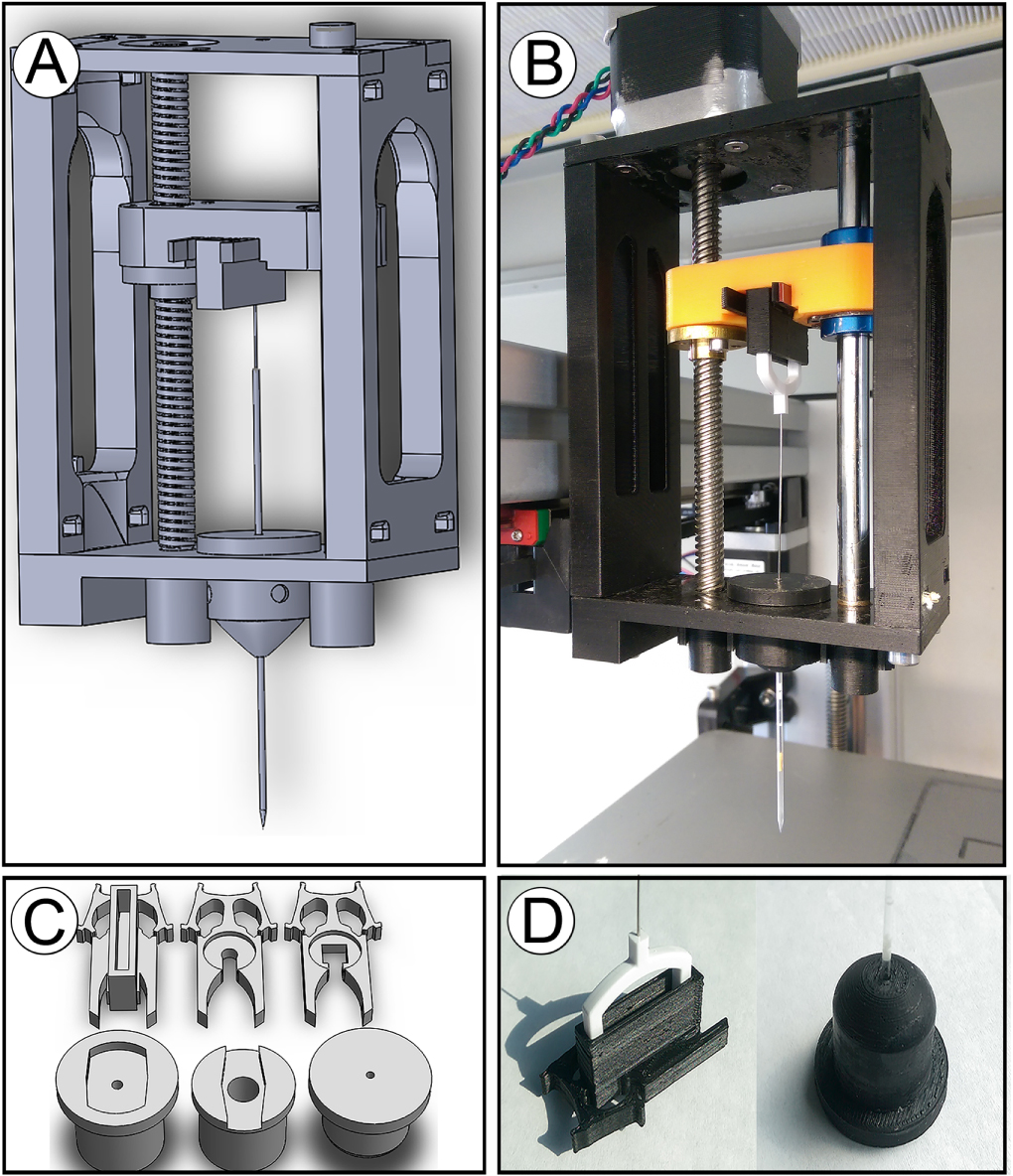
Most well-appointed commercial 3D bioprinters cost well above the budget limits of many biological laboratories wishing to use these tools for cell based experimentation. To address this we aimed to use readily available parts to adapt an 'off the shelf' extrusion-based 3D printer into a high-precision, open-sourced bioprinter. The unmodified Felix has a positional resolution within a reasonable range for single cell deposition. We used computer-aided design (CAD) software to design a microextrusion apparatus to replace the plastic extruding print head, figure 1(a). These prototype parts were then 3D printed using the standard extrusion system on the unmodified Felix system, figure 1(b). To better serve our experimental requirements, the system was designed to be interchangeable with more than one type of plunger-driven syringe system (several sizes of luer-lock syringe, microcapillary pipettes, etc), figure 1(c). Our 3D printed parts were highly accurate with regard to matching specified part dimensions, figure 1(d). Furthermore, no measurable differences among printed components were observed confirming the Felix's stated precision and accuracy.
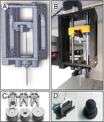
Figure 1. CAD design and 3D printing of bioprinter modifications to the Felix 3.0: (a) CAD model of x-axis bioprinting adapter with lead screw and syringe adapter for injector depression. (b) Resultant 3D-printed bioprinter injector adapter mounted to the x-axis of 3D printer with stepper motor installed for injector actuation. (c) CAD models for syringe adapter inserts for securing the body of the injector (bottom row) and clips for holding the plunger (top row). (d) Example of a 3D printed insert and clip used with the pulled glass-microcapillary pipette injector and Teflon plunger.
Download figure:
Standard image High-resolution image3.2. Needle optimization through computational modeling
As we intended to use our 3D bioprinter to print liquids containing both biomolecules and sensitive cell types, we recognized the need to model various needle variants to determine the flow characteristics, including shear rates in the needle tip. To do this, we designed several permutations of needle types using 3D CAD software. The needle types of our initial simulations included a model of a conventional syringe-needle system, and needles with various lengths and internal slopes with a straight-sided triangular, T, or parabolic curved, C, geometry. The straight triangular needle is characterized by having a linear change in needle diameter, whereas the curved needle types resemble more of a parabolic curve with a slope that is greater than one (see [24] for more information). We then measured the impact of needle geometry on fluid dynamics during the bioprinting process using computer generated, multiphysics simulations. To provide a better understanding of needle clogging due to cell accretion, we traced particle streamlines of 10 μm wide particles, the typical diameter of cells, through our needle models under conditions that favored aggregation. The aggregation of cells within the needle tip occurred by increasing particle accretion rates and lowering the normal and tangential coefficients of restitution at the needle wall. Particle studies then indicated a large population of cells with velocities near zero in the narrowest region of the conventional needle configuration, figure 2(a). These populations were not observed in triangular needle configurations, figure 2(b). This indicated the conventional needle type leads to a higher rate of cell aggregation and needle clogging when compared to a tapered, triangular needle. Furthermore, the results from the flow simulations also indicated cells traveling through the center of the conventional configuration have a higher velocity than those in the center of the straight triangular configuration, 75 mm s−1 versus 55 mm s−1, respectively. Interestingly, when the duration of the simulation was increased, we observed particle streamlines in the conventional configuration that travel away from the needle entrance.
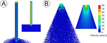
Figure 2. CFD particle studies of the bio-deposition process under conditions that favor aggregation. Heat map graphical representations of particle velocities of 10 μm wide particles, the typical diameter of cells, traveling through idealized microneedle geometries representing: (a) conventional 'luer-lock' needle type and (b) triangular needle configurations under conditions of steady, non-Newtonian flow with a constant volumetric flow rate of 0.1 mm3 s−1. The inlet and exit diameter for all needle conditions equaled 1 mm and 60 μm, respectively. The flow outlet boundary condition equaled standard atmospheric pressure (101325 Pa). Our model conditions accounted for the effects of gravity. The exit velocity for the conventional 'luer-lock' condition (a) was 72 mm s−1, whereas the triangular needle (b) was 55 mm s−1. The aggregation of cells within the needle tip was encouraged by increasing particle accretion rates and lowering the normal and tangential coefficients of restitution at the needle wall. Under these conditions, particles near the exit of the microneedle with zero velocity (shown in blue) were only observed in the conventional 'luer-lock' geometry types.
Download figure:
Standard image High-resolution imageThe velocity profile established in a given flow situation strongly influences the mass transfer process. For the process of bioplotting, the mass transfer process is primarily dependent on the ability of the ejected droplet to remain inside the surrounding material. Furthermore, the needle tip should also impart minimal damage to the gel during the plotting procedures. Therefore, the best needle type should be narrow enough to penetrate the gel without disturbing surrounding material, limit unfavorable processing conditions for fragile cell types, and perform the printing process without clogging. To examine this concept a comparison between triangular, T, and curved, C, needles of increasing length was performed. The resulting data indicated all T type needles have a higher average velocity than C type needles. Interestingly, we found the maximum velocity was greatest in the 1 mm long needle type (table 1). Yet, the 1 mm long T type requires lower force and results in a lower maximum pressure than both 7 mm long needle types. Given the inlet diameter for these simulations equaled 1 mm, the 1 mm long straight needle represents a 1:1 geometry near that of a straight-sided cone. We also found conically shaped needles generate less internal pressure than straight-sided triangular needles of the same length. Numerical results indicate needle length has a significant effect on total pressure. Interestingly, the 7 mm C needle type, showed a sharp reduction in total pressure when compared to a straight-triangular needle type of the same length, 7 mm T. We found this relationship to suggest needle length and needle type has an effect on total pressure. While longer needle lengths resulted in higher total pressures, the C type needles were always lower in total pressure than the straight-triangular type of the same length. Overall, the results show that as the cross-sectional area of the microneedle decreases, the maximum fluid velocity increases and the pressure decreases.
Table 1. Analytical solutions to CFD simulations of the bioprinting process using various microneedle geometries.
| Needle type | Avg. pressure (kPa) | Max. pressure (kPa) | Avg. velocity (mm s−1) | Max. velocity (mm s−1) | Applied force (N) |
|---|---|---|---|---|---|
| 7.0 mm Ta | 107.679 | 107.712 | 17.109 | 719.010 | 0.001 017 152 |
| 7.0 mm Cb | 103.505 | 103.526 | 15.339 | 711.593 | 0.000 352 58 |
| 1.0 mm Ta | 103.109 | 103.124 | 17.569 | 1271.699 | 0.000 283 929 |
| 1.0 mm Cb | 102.862 | 102.870 | 11.146 | 1249.325 | 0.000 139 728 |
| 0.75 mm Ta | 102.200 | 102.227 | 17.176 | 837.077 | 0.000 139 728 |
| 0.75 mm Cb | 101.683 | 101.691 | 11.157 | 746.944 | 0.000 056 1757 |
aNeedle tips with a straight-sided, triangular appearance. bNeedle tips with curved geometries.
Results from our flow simulations also found the shear rate generated in conventional systems is greater than shear rates observed in needles with tapered geometries. These simulations show how as the extent and shape of the flow passages change, the cells within the fluids are subjected to stretching in one or more dimensions. It should be noted the shear rate in the conventional system was highest in the region immediately after the abrupt reduction in needle diameter, and in the region nearest the needle tip, suggestive of elongational flow, figure 3(a). On the other hand, the shear rate observed in needles with a straight triangular taper is greatest in the region of the tip, figure 3(b). Furthermore, we were able to generate this post-constriction increase in shear rate in tapered needle types by increasing the length of the narrowest section of the needle (data not shown). Using the results from our simulations, three microneedle geometry types were fabricated using a programmable pipette puller. The programmable pipette puller and our glass pipettes provided the ideal process to fabricate of many custom needle configurations. To provide a comparison to the standard 28 gauge stainless steel needle, these three types are shown in figure 3(c). The three needle types shown in figure 3(c), from left to right, are examples of a 3 mm long straight-triangular needle with a 150 μm tip diameter, a 5 mm long curved needle with 150 μm diameter, and a 6 mm long curved needle with a 75 μm diameter. One notable difference between the conventional needle and our pulled needles is the length of the narrow channel. The narrowest section of the conventional, stainless-steel needle is typically 30 mm long, which is five times longer than the typical length of our fabricated needles (∼5 mm). Using needles with geometric features that minimize the amount of time cells travel through these narrow channels presents fewer opportunities for cells to aggregate and a concurrent reduction in detrimental forces, both of which are a significant process improvement. Furthermore, by fabricating the needle from borosilicate glass tubes we were able to retain a high degree of structural rigidity without the need to increase the thickness of the needle wall. That is to say, the ratio of the outer-diameter to the inner-diameter is substantially lower for the glass needles than the conventional steel needle, figure 3(c). This provided a substantial increase to the print resolution of our system. The conventional needle was not capable of the same degree of positional precision and repeatability as the glass needle. When compared to glass, the thin stainless-steel needle has more elastic material properties, which made it prone to bending during the printing process. The nonlinearity across the needle meant the needle tip was not always precisely above the target site. This also negatively impacted the plotting process by introducing insertion angles that were not always perpendicular to the target site, which resulted in increased disruption of the gelled material surrounding the target site. While we initially began our experimentation with a narrower 30 gauge needle, the high concentration of cells required for the printing process made printing through such long narrow needles unreliable due to frequent clogging. Through further experimentation, we found a 28 gauge needle provided the required performance for our experiments. Despite the 25 μm increase in interior needle diameter than a 30 gauge needle, using 28 gauge needles did not completely alleviate the clogging issue. It should also be noted that the 28 gauge needle has an inner diameter four times larger than the pulled glass microneedles. Overall, borosilicate glass tubes which combine the needle and syringe into a single, rigid part with geometry optimized for fragile cell transfer are superior to conventional, stainless-steel needles.

Figure 3. Shear rate results from CFD particle studies of the bio-deposition process using various microneedle geometries. 10 μm wide particles, the typical diameter of cells, traveling through idealized microneedle geometries representing: (a) conventional 'luer-lock' needle geometry, (b) triangular needle geometry under conditions of steady, non-Newtonian flow with a constant volumetric flow rate of 0.1 mm3 s−1 (0.1 μl s−1). The inlet and exit diameter for all needle conditions equaled 1 mm and 60 μm, respectively. The flow outlet boundary condition equaled standard atmospheric pressure (101325 Pa). Our model conditions accounted for the effects of gravity. Simulated results indicated cell sized particles travel through areas with greater amounts of shear in conventional 'luer-lock' needles than straight-sided triangular needles. (c) Examples of pulled-glass microcapillary tubes with tapered geometries (left to right): 3 mm long straight-triangular needle with a 150 μm tip diameter, 5 mm long curved needle with 150 μm diameter, 6 mm long curved needle with a 75 μm diameter, and 28 gauge stainless steel needle.
Download figure:
Standard image High-resolution image3.3. Cell viability assay
To further study the effects of microneedle geometry on the dynamic process of bioprinting, we sought to determine if there was an appreciable real world impact seen when applying the various needle permutations. To accomplish this we used an immortalized, non-tumorigenic, adult mammary epithelial cell line, MCF-12A. Following injection into 96-well plates, the cells were assayed for metabolic activity 1 h post printing and then again 96 h post printing. Results from the AlamarBlue assay indicated a significant reduction in the amount of viable cells 1 h post-printing for the syringe-28 Gauge needle condition compared to control (no-tip) for two printing speeds, 600 μl min−1, 1000 μl min−1 (figure 4(a), *p < 0.05). This experimental data supports results from our simulations. A significant increase in viability was also observed 96 h post-printing for the 1000 μl min−1, straight-cone or triangular condition, compared to control, (figure 4(b), *p < 0.05). These data confirmed that while survival was comparable amongst many of our needle designs, when print speeds increase, a corresponding reduction in viability is observed in needles that were previously shown to have a greater shear rate. This is likely due to the initial stress placed upon the cells resulting in a lack of cellular division during the 96 h post-print.

Figure 4. MCF-12A AlamarBlue cell viability studies post-printing. (a) AlamarBlue reduction 1 h post-printing (*p < 0.05), (b) AlamarBlue reduction 96 h post printing (*p < 0.05). MCF-12a cells were suspended in media to a concentration of 1 × 10⁶ cells ml–1. For all conditions, approximately 25 μl of cell containing media was loaded into the needle at a rate of 10 μl min−1 and dispensed into wells of a 96 well plate at one of four rates: 100, 400, 600, and 1000 μl min−1. All four rates were repeated in three separate wells for a total of 12 wells per condition. Four needle conditions; no-tip (control), 28 gauge needle, straight cone, and long tapered needle were tested, giving a total of 48 wells. The sample mean viability was calculated and normalized to the initial viability of the no-tip control. Statistical significance was determined using one-way ANOVA with Dunnett's post hoc test (p < 0.05). Error bars, mean ± s.d.
Download figure:
Standard image High-resolution image3.4. Print resolution verification
As the diameter of most somatic human cells are between 10–30 μm, and the spacing between injection points is largely determined by the diameter of the needle, we wished to generate a system capable of printing as close to this target range as possible. Precise placement of different cell types or signaling molecules and other various components in as close proximity to a 'cellular' resolution would be highly advantageous. To test the limits of printed cell resolution and the possibility of obtaining single cell extrusion events, we injected 1 nl of media containing GFP labeled MDA-MB-468 cells into ∼1 mm thick Geltrex, figure 5(a). To provide better illustration of this process, figures 5(b)–(d) represent GFP, bright-field, and combined channels of the single cell 'events' our system generates. Analysis of the single-cell extrusion events indicated our system is capable of reliably extruding single cells. To further examine the capacity of our printer, we quantified the distances among printed cell locations using ImageJ software to define positional precision. This analysis found the X and Y resolution to be ±6.34 μm and ±9.71 μm, respectively, confirming the factory-listed resolutions (13 μm × 13 μm (±6.5 μm)). In addition to positional precision, bioprinting techniques also require precise control over the amount of extruded material. To determine how effective our printer was at controlling the amount of extruded materials, we generated a gradient of GFP labeled rat epithelial cells by decreasing the extrusion amount in each successive row from 70 nl , 60 nl, 50 nl and 10 nl, figure 5(e). Upon manual counting, the number of cells within each print location, from top to bottom, averaged 68 ± 6, 62 ± 4, 51 ± 4, and 8 ± 2, respectively. The theoretical cell concentration in the media used to generate the gradient study in figure 5(c) represented a distribution of 1 cell per nl. Given this information, we observed an overall congruency among the number of counted cells and the directed extrusion amount. The variation in the number of printed cells was greatest in row one, the group with the largest extrusion amount. We expected to observe greater variation in the number of cells in the larger extrusion conditions because our approach is largely based on pairing the probability of a single cell within a specified extrusion amount. The duration of the plotting procedure was less than 3 min. Therefore, it appears printing within this time window prevents confounding variables such as cell settling due to gravity. The results in figure 5 provide information on the ability of the system to repeatedly handle volumes from 1 to 100 nl. Furthermore, they provide insight into our systems ability to repeatedly extrude a set number of cells within a single target volume.
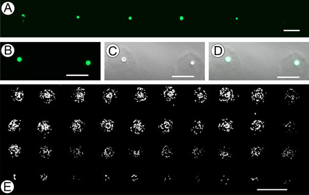
Figure 5. Printer resolution and functional limitations. (a) 1 nl extrusion, each containing a single GFP labeled MDA-MB-468 cell printed into ∼1 mm thick Geltrex (scale bar 100 μm). (b) GFP channel of single-cell extrusion event using MDA-MB-468 cells (scale bar 100 μm). (c) Bright-field channel of the same single-cel extrusion event (scale bar 100 μm). (d) Combined GFP and bright-field (scale bar 100 μm). (e) Decreasing gradient of GFP labeled rat epithelial cells generated by extruding 70 μl, 60 μl, 50 μl, and 10 nl (scale bar 300 μm).
Download figure:
Standard image High-resolution image3.5. Bioprinted hiPSCs
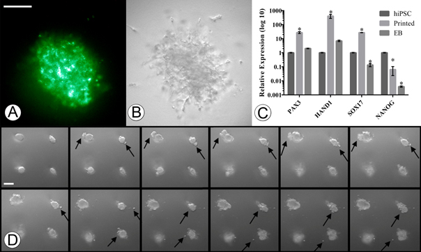
Bioprinting of pluripotent cells in order to generate biomimetic embryonal structures is a crucial step for disease modeling and tissue engineering. However, the printing process can physically alter the cellular structure resulting in unwanted shifts in gene expression and protein function. Having previously determined our extrusion system has minimal shear and pressure related effects on cells, we hypothesized that our system would have no negative impact on hiPSCs printed into either differentiation or pluripotent-conducive environments. We first wanted to determine if our system was capable of printing hiPSCs that retain their pluripotency post-printing. To test this we used our pulled glass needles to print 3D aggregates of hiPSCs using pluripotency-conducive E8 media into growth factor reduced Geltrex. Following 7 d post printing of the iPSCs we then stained the aggregates with pluripotency antibody TRA-1-81, a cell surface marker specific for pluripotent cells (figure 6(a)), confirming that our system is capable of retaining a pluripotent state.
Figure 6. 3D printed hiPSCs. (a) Presence of green fluorescence due to TRA-1-81 binding to undifferentiated pluripotent cells in 3D printed hiPSC aggregate 7 d post printing. (b) Bright-field image of 3D printed hiPSC aggregate. (c) Gene expression profiles of hiPSCs using markers for ectoderm (Pax 3), mesoderm (Hand 1), endoderm (Sox-17), and pluripotent marker (Nanog) (*p < 0.01). Error bars, mean ± s.d. (d) 7 d-time lapse images of bioprinted hiPSCs in a 1:1 mixture of Geltrex/differentiation supportive media reveal dynamic growth and increased complexity (left to right, top-left taken at t0) (scale bars 100 μm).
Download figure:
Standard image High-resolution image
We next wanted to test the ability of our system to generate differentiated EBs. To confirm the differentiation of our injected hiPSCs, we compared their gene expression changes to the gold-standard hanging-drop EB method. We therefore printed hiPSC in Geltrex (500 cells per injection) with FBS containing media and in tandem deposited hiPSCs on culture flask lids (500 cells per droplet) and following lid inversion, allowed them to incubate at 5% CO2, 37 °C for 7 d. To then evaluate and confirm that the differentiated EBs were similar in nature, mRNA was extracted and qRT-PCR was performed. The results of our gene expression assays indicated a significant up-regulation of differentiation markers for the endoderm (Sox17), mesoderm (Hand1), and ectodermal (PAX3) lineages in the printed hiPSC group as compared to non-printed, non-differentiated control hiPSCs, (figure 6(c), *p < 0.01). Interestingly, the gene expression was also significantly upregulated as compared to the hanging drop EBs, possibly indicating a more mature differentiation. To observe the motility and growth of our injected hiPSCs we followed the injections with time-lapse imaging. This revealed the initial formation of spheroids followed by the dynamic growth of secondary and tertiary structures similar to budding, elongation, and increased complexity over 7 d, figure 6(d) (supp. movie 1–3).
4. Discussion
Using 3D printed parts and highly accessible hardware, we were able to reliably print at precise XYZ locations within 3D hydrogels cellular aggregates in various concentrations with injection volumes ranging from 1 nl to hundreds of microliters with spatial resolution only limited by the diameter of the needle itself. Currently, our system is able to obtain prints containing 1 cell per injection event. We attribute part of this cellular resolution to the use of stepper motors, which are ideally suited for extrusion-based bioprinting as they offer a unique solution for open-loop position control. Specifically, the output shaft rotates in a series of discrete angular intervals, or steps, each time a command pulse is received, therefore the exact displacement of the shaft is known at all times. This feedback allows the user to modify the acceleration rates and deceleration rates of the fluid while traveling through the needle at all times during 3D printing experiments. This forward/reverse positional control gives an additional level of process control unseen in solenoid valve based systems that have been previously examined [13, 16]. Additionally, the shaft of the motor will remain at a specific step until another step pulse is supplied, which provides exceptional positional control and eliminates leaks from the needle tip.
It is known that the fluid characteristics during syringe needle flow introduce three main types of mechanical forces capable of cell disruption: (i) shearing forces due to linear shear flow, (ii) pressure drop across the cell, and (iii) stretching forces due to extensional flow [20]. Numerous studies have implemented novel hydrogel-vehicle systems as a sacrificial, viscoelastic material to encapsulate cells and alter the distribution of damaging mechanical forces experienced during flow [20, 21, 25, 26]. Yet, despite encapsulation in alginate solution (1.5% w/v), one study found ink-jet dispensing pressure demonstrated a more significant effect on cell viability than nozzle diameter; constructs printed at 40 psi showed a 38.75 percent reduction in viability compared to those printed at 5 psi [27]. Recently, Faulkner-Jones et al found an effect of nozzle length and dispensing pressure on human pluripotent stem cell viability; cells printed through an 8.9 mm long nozzle showed higher levels of viability than those in a 24.4 mm long nozzle [16]. We therefore tested if injection systems which impart the lowest amount of overall shear would be preferable for fragile cell transfer; and those systems which minimize the amount of time a cell flows through the highest shear-rate section of the needle (or nozzle) would be preferable to systems in which the cells spend a greater amount of time flowing through high shear-rate sections.
To investigate this we compared the force distribution of several needle types using FEM to identify features related to cell damaging forces. This approach enabled us to examine the development of these forces throughout the bioprinting process using systems of equations that included boundary conditions with slip along the needle wall. Mathematical models have been developed which indicate tapered needle geometries result in different cell damages due to the conical geometry and changing force distribution in the needle. Billiet et al found a significant pressure and needle type dependence on cell viability; at low inlet pressure, conically shaped needles are preferred over cylindrically shaped ones [28]. However, they found this advantage disappears at higher inlet pressures, yet they did not vary the length of the needle or the angle of the needle tip in their studies. Our investigation found short, conically shaped needles are preferred over long cylindrically shaped geometries due to a favorable axial pressure gradient that requires less energy to accelerate fluid through the microneedle, and a substantial reduction in the amount of shear in the needle tip. When the cross-section of a pipe gradually narrows, such as the straight-triangular needle in figure 3(b), the streamlines follow closely along the contours of the pipe and virtually no extra frictional losses are observed. By generating a more even transition to the narrow diameter needle tip, tapered needles provide a better-suited environment for fragile cell transfer. Furthermore, when this transition is abrupt, such as those of the conventional 'luer-lock' configurations, the inner diameter of the syringe is notably larger than the needle tip, and the cells undergo a correspondingly abrupt increase in linear velocity as they pass into the needle, also known as extensional flow. This convergence to a small point, coupled with the increased shear seen in the long, cylindrical needle appear to be the two components that contribute to unfavorable printing conditions related to fragile cell transfer. With these hypothetical variations in mind, we confirmed that syringe-needle extrusion rates greater than 600 μl min−1 have an effect on cell viability when compared to no-tip controls. Additionally, when examining the 96 h post injection viability it was clear that extrusion velocity and the needle geometry had a significant effect on growth.
3D based organogenesis from hiPSCs is one of the most exciting areas of tissue engineering and biofabrication. The approach of self-organizing pluripotent cells into functional differentiated cells not only represents a better model of natural processes, but also serves as a highly efficient method of organogenesis. Our investigation provides essential information on how biofabrication parameters such as needle geometry and flow rates may affect the post-printing behavior of hiPSCs. Positive TRA-1-81 staining of hiPSC printed aggregates in pluripotent supportive environments, indicate our printing device was capable of delivering unaltered pluripotent cells into 3D environments without the need for protective encapsulation strategies. Furthermore, when these same pluripotent cells were injected into differentiation signaling environments, the printed hiPSC aggregates generated small, spherical cluster of cells that then began to depart from the main body and appeared to wander through the 3D matrix. Interestingly the gene expression analysis revealed a significant increase in differentiation and pluripotent markers as compared to both the non-differentiated iPSC and the standard EB formation methods. It is known that the physical features of the surrounding structure affect the differentiation of stem cells, therefore, one way to explain the increase in relative expression of these genes in the printed group, when compared to the non-printed control, may be due to an interaction among the hiPSCs and 3D gel-matrix. Instead of directly mixing these highly sensitive cell types with the scaffold materials required to generate 3D structures, our approach sought to prevent these types of cell-structure interactions by placing cells into specific 3D locations inside a pre-formed, 3D architecture. Because these cells are not directly included in the fabrication process, which often requires the structural change of the scaffold from a liquid to a gel post-printing, this method attempts to eliminate these types of extraneous variables in order to better understand the differentiation pathways that iPSCs follow when placed in a 3D environment. This feature could expose many future advantages that would establish a better understanding of normal tissue and organ development. This holds many benefits for developing models that better mimic human disease as well as affording us the capability to design and construct accurate replacement cellular constructs.
5. Conclusion
Here we have described a simple process for development of an accessible and high precision 3D bioprinter through modification of an inexpensive 'off the shelf' 3D printer. The bioprinter uses a pulled-glass capillary pipette to minimize shear stress and optimize positional control and precision. This minimal cellular impact enabled our system to successfully print hiPSCs while maintaining their pluripotency. Additionally, we were able to print hiPSCs into differentiation conducive environments that generated cells of all three developmental germ-layers. To the best of our knowledge, our system is the first 3D printed, bioprinting system to reliably achieve single cell print resolutions within 50 μm resolution, while also exerting minimal unwanted impact on the cells viability and post-printing fate. Furthermore, our system is highly modifiable and can be fabricated for use on any 3D printer. This type of system is ideal for adaptation by both basic and clinical research laboratories for the study of cellular interactions and/or tissue engineering applications. We would like to note that our bioprinting system upgrade cost less than $200 (not including the off-the-shelf printer, which could be substituted for other models). Our hope is our system, or similar systems will lower the technical and financial hurdle of 3D bioprinting to any laboratory with an interest in furthering the developments of 3D cellular biology. As open-sourced projects have developed advanced software systems such as Unix, and hardware solutions such as Arduino and Raspberry Pi, here we institute similar initiatives within the field of biofabrication. To facilitate this, our models are freely available for download from our repository (http://ww2.odu.edu/~psachs/Sachs_Lab/3D_BioPrinter.html).