
Abstract
Novel additive manufacturing processes are increasingly recognized as ideal techniques to produce 3D biodegradable structures with optimal pore size and spatial distribution, providing an adequate mechanical support for tissue regeneration while shaping in-growing tissues. With regard to the mechanical and biological performances of 3D scaffolds, pore size and geometry play a crucial role. In this study, a novel integrated automated system for the production and in vitro culture of 3D constructs, known as BioCell Printing, was used only to manufacture poly(ε-caprolactone) scaffolds for tissue engineering; the influence of pore size and shape on their mechanical and biological performances was investigated. Imposing a single lay-down pattern of 0°/90° and varying the filament distance, it was possible to produce scaffolds with square interconnected pores with channel sizes falling in the range of 245–433 µm, porosity 49–57% and a constant road width. Three different lay-down patterns were also adopted (0°/90°, 0°/60/120° and 0°/45°/90°/135°), thus resulting in scaffolds with quadrangular, triangular and complex internal geometries, respectively. Mechanical compression tests revealed a decrease of scaffold stiffness with the increasing porosity and number of deposition angles (from 0°/90° to 0°/45°/90°/135°). Results from biological analysis, carried out using human mesenchymal stem cells, suggest a strong influence of pore size and geometry on cell viability. On the other hand, after 21 days of in vitro static culture, it was not possible to detect any significant variation in terms of cell morphology promoted by scaffold topology. As a first systematic analysis, the obtained results clearly demonstrate the potential of the BioCell Printing process to produce 3D scaffolds with reproducible well organized architectures and tailored mechanical properties.
Export citation and abstract BibTeX RIS
1. Introduction
The loss or failure of an organ or tissue is a frequent, devastating and costly problem in health care. The need for substitutes to replace or repair tissues or organs due to disease, trauma or congenital problems is overwhelming. As reported by the United Network for Organ Sharing (UNOS), in 2011 there were 118.222 patients in the USA awaiting for organ transplantation [1]. The shortage of donors and the side effects of immunosuppressive agents remain paramount challenges in terms of organ transplantation. As an example, in the case of bone tissue replacement, when the body itself is not able to produce enough material to fill the bone defect, different chirurgical procedures may be adopted. The actual gold standard remains autogenous bone grafting (bone parts are harvested from the patient himself and implanted at the defect site), but not without shortcomings, namely long recovery periods, donor site morbidity and the complex graft shaping process (in order to achieve a perfect biomechanical coupling at the defect site) [2–7]. Natural bone graft materials can also be obtained from other sources such as donators of the same species (allografts) or animals (xenografts). Although avoiding the morbidity aspect associated with autografts, the low mechanical performances along with the probability of immuno-rejection, inflammation and disease transmission clearly limit their use. Because of the abovementioned reasons, tissue engineering (TE) is clearly becoming an important field of research, where a broad range of experts combine their knowledge and efforts in order to develop new clinical approaches for the regeneration/restoration of damaged tissues. The most promising approach in TE involves the seeding of porous biocompatible/biodegradable scaffolds with donor cells to promote tissue regeneration [8]. The essential requirements for these 3D structures have evolved over the years; nowadays they are no longer expected to act only as passive structural matrices capable of supporting cell adhesion/proliferation but also to act as 3D carriers for the delivery of bioactive molecules to enhance tissue regeneration [9–13]. Reviewing the literature, it is possible to conclude that due to the functional multitude of the tissues it becomes very complex, if not impossible, to establish what defines the ideal scaffold, even for a single tissue type [14]. The considerations are complex and include chemical, morphological, mechanical and biological factors and their mutability with time. Nonetheless, it is well recognized that pore size plays an important role in terms of cell adhesion/differentiation/migration, vascularization and new tissue ingrowth [10, 15–19]. Many researchers have reported optimum pore size ranges according to the different cell lines, tissues and materials. [19–22]. Despite the great variability observed in the results obtained by different researchers, it seems to be widely accepted that pore size alone is not able to assure an appropriate bone ingrowth and proliferation, which also greatly depends on pore interconnectivity. Therefore, more accurate and systematic evaluations on optimum pore size ranges of scaffolds still need to be performed.
Basically, the importance of using polymer-based materials and different techniques to make multifunctional scaffolds/substrates characterized by specific architectural, structural and rheological features has also been properly stressed in literature [23–38].
With regard to scaffold manufacturing processes, several techniques have been developed. In this context, when introduced in the biomedical field, additive manufacturing (AM) technologies have led researchers to divide scaffold fabrication processes into two groups: 'conventional' and 'non-conventional' methods. Conventional techniques encompass gas foaming, solvent casting/particulate leaching, fibre meshes/fibre bonding, solution casting, phase separation, emulsion freeze drying, melt moulding and freeze drying [39–41].
Interconnectivity, pore size and geometry are critical for the mechanical and biological performances of the scaffolds, influencing not only their mechanical behaviour, but also the degree and the path of tissue regeneration [41–47].
However, conventional methods are not able to precisely control pore size and geometry, as well as the spatial distribution of pores, thus lacking any long-range channelling micro-architecture [39–44].
Moreover, scaffolds manufactured using conventional techniques can be suitably shaped with custom-made moulds.
Accordingly, further fabrication processes as a new group of non-conventional techniques have been introduced in the biomedical field to overcome the drawbacks related with conventional methods [48].
Specifically, the introduction of AM represents the possibility of manufacturing customized scaffolds with very complex 3D shapes, a reproducible internal morphology and architectural control, increasing the mass transport of oxygen and nutrients throughout the scaffold [10, 39]. The collective term AM refers to a group of technologies that can manufacture objects in a layer-by-layer manner starting from a 3D computer design of a specific object [39–41, 47, 49–51].
Different AM technologies have been developed to manufacture scaffolds for TE applications, including ink-jet printing, fused deposition modelling, stereolithography, laser sintering and a few other extrusion-based technologies, such as 3D plotting and 3D fibre-deposition [41, 47, 52–62].
In this study, a novel integrated biomanufacturing system, known as BioCell Printing, is proposed to fabricate poly(ε-caprolactone) (PCL) scaffolds characterized by a homogeneous spatial distribution of pores and fully interconnected internal channels. The flexibility and versatility of this extrusion-based technology in developing scaffolds for TE were already demonstrated by the authors in previous works [30]. The potential and feasibility of this novel AM technology opened the opportunity to study with a high level of accuracy how structural features (lay-down pattern and filament distance (FD)) influence the mechanical performance of the 3D rapid prototyped scaffolds. This study should represent the first systematic approach in analysing the performance of 3D PCL scaffolds manufactured through Biocell Printing, with a special focus on the effect of pore size and geometry on the compressive mechanical behaviour and on the in vitro biological behaviour (e.g. cell adhesion, viability/proliferation) of human mesenchymal stem cells (hMSCs).
2. Materials and methods
2.1. Materials
PCL (CAPA 6500, Mw = 50 000 Da) in the form of 3 mm pellets was obtained from Perstorp Caprolactones (Cheshire, United Kingdom) and used as received for the production of the scaffolds.
With regard to the fabrication of the PCL structures, a novel integrated biomanufacturing device called BioCell Printing was employed, equipped with an extrusion nozzle of 300 µm. The system enables the fabrication of functional TE matrices through the integration and synchronization of the production, sterilization, cell seeding and dynamic in vitro culture (bioreactor) zones (figure 1).

Figure 1. Schematic representation of BioCell Printing with the different zones. (a) Construction; (b) sterilization; (c) cell seeding; (d) in vitro culture.
Download figure:
Standard image High-resolution imageA detailed description of the instrument along with the flowchart information required for the fabrication of scaffolds for TE applications can be found elsewhere [30]. Briefly, rectangular prisms measuring 30 mm (length) × 30 mm (width) × 8 mm (height) were initially designed using a computer-aided design software (SolidWorks, Dassault Systèmes SA). Afterwards, imposing a single lay-down pattern of 0°/90° and varying FD values from 550 to 750 µm, it was possible to produce scaffolds with square interconnected pores of different dimensions and porosity levels (figure 2).

Figure 2. Schematic representation of a cross section viewed in the XZ plane of the building process and the 3D structure of the rapid prototyped scaffolds characterized by a 0°/90° lay-down pattern. Symbols are denoted as RW: road width or filament diameter; FG: filament gap; ST: slice thickness; LG: layer gap; FD: filament distance (centre to centre).
Download figure:
Standard image High-resolution imageIn terms of pore shape, three lay-down patterns were adopted (0°/90°, 0°/60°/120° and 0°/45°/90°/135°) maintaining a regular FD of 650 µm, resulting in scaffolds with quadrangular, triangular and complex polygonal internal pore geometries, respectively (figure 3).
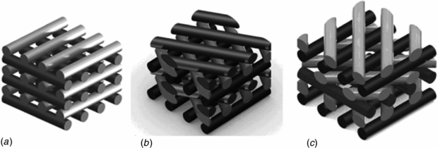
Figure 3. Schematic representation of rapid prototyped scaffolds characterized by three different lay-down patterns. (a) 0°/90°. (b) 0°/60°/120°. (c) 0°/45°/90°/135°.
Download figure:
Standard image High-resolution imageTable 1 shows the common process/instrument parameters used to manufacture all the scaffolds.
Table 1. Process/instrument parameters used to develop rapid prototyped PCL scaffolds. Deposition velocity (DV), slice thickness (ST), liquefier temperature (LT), extrusion pressure (EP) and screw rotation velocity (SRV).
| Process/instrument parameters | ||||
|---|---|---|---|---|
| DV (mm s−1) | ST (µm) | LT (°C) | EP (bar) | SRV (rpm) |
| 10 | 280 | 80 | 5 | 30 |
All of the scaffolds were then cut into smaller blocks of required dimensions for further analyses.
2.2. Scaffold characterization
2.2.1. Morphological and mechanical characterization
Morphological analysis of the 3D rapid prototyped structures was carried out using a scanning electron microscope (SEM, FEI Quanta 600 F) to visualize and evaluate the physical integrity of the material filaments and layers, as well as verifying if the pore size and geometry obtained were consistent with the theoretical values imposed during the fabrication process.
The porosity was evaluated using the following methodology: (1) measuring the weight and volume of each sample, (2) calculating the apparent density of the PCL scaffolds, (3) applying the formula reported below:

where ρ* is the apparent density of the cellular structure (scaffold) and ρsub is the density of the original substance (ρsub = 1.145 g cm−3). Five samples were measured for each scaffold morphology [63].
Compression tests were performed on the 3D rapid prototyped scaffolds in order to highlight the effect of the FD, i.e. centre-to-centre distance (550, 650 and 750 µm) and lay-down pattern (0°/90°, 0°/60°/120° and 0°/45°/90°/135°) on the mechanical properties.
Each block-shaped specimen was characterized by a length (l) of 5.0 mm, a width (w) of 5.0 mm and a height (h0) of 8.0 mm. All the tests were carried out on scaffolds at a rate of 1 mm min−1 up to a strain value of 0.5 mm mm−1, using an INSTRON 5566 testing system.
The 'apparent' stress σ was evaluated as the force F measured by the load cell divided by the total area of the apparent cross section of the scaffold (A = l w):

while strain ε was defined as the ratio between the scaffold height variation (Δh) and its initial height (h0):

Mechanical results were reported as mean ± standard deviation and were analysed using the analysis of variance followed by Bonferroni post-hoc comparisons. Statistical differences were set at p < 0.05.
2.2.2. Cell adhesion/proliferation assay
Cell-seeding experiments were carried out using hMSCs (Clonetics, Italy) to provide insight into the effect of pore size and shape on cell adhesion and viability/proliferation.
PCL scaffolds were cut into disc shaped blocks with appropriate dimensions in order to fit inside the 12 well plate, sterilized with a 70% ethanol/water solution for 24 h, washed extensively with PBS 0.01 M pH 7.4 and exposed to UV light for 40 min.
Afterwards, 17 × 103 cells were re-suspended in 200 µL of α-modified Eagle's medium (α-MEM) (Bio-Whittaker, Belgium), statically seeded directly onto the PCL scaffolds and allowed to proliferate for 21 days. At pre-determined intervals (7, 14 and 21 days) the samples were withdrawn from the incubation media, rinsed with PBS (Sigma-Aldrich, Italy) and analysed by means of an Alamar Blue™ assay as described in previous works [26].
Cell morphology was investigated by confocal laser scanning microscopy (CLSM, Zeiss LSM 510/ConfoCor 2). After the permeabilization step with Triton X-100, samples were incubated with a PBS 0.01 M solution of Phalloidin for 45 min at room temperature. After the dyeing incubation, scaffolds were washed with PBS before being mounted on a glass slide and sealed with resin for microscopic observation.
Confocal images obtained from all the cell-scaffold constructs were also suitably analysed through Image J software (National Institutes of Health, USA) to assess the cell morphology using a shape factor.
The shape factor was expressed as follows:

where Θ represents a geometric constant (4π) related with the footprint area and P is the perimeter of a cell. Considering that circular objects have the greatest area-to-perimeter ratio, a shape factor of 1 represents a perfect circle. Conversely, a thin thread-like object possesses the lowest shape factor approaching zero [64].
3. Results and discussion
The colonization of 3D porous matrices is dependent on many factors including architectural features such as pore size/shape, interconnectivity, overall scaffold porosity and topography. It is well recognized that pore size and shape can actually influence cell adhesion, migration and tissue ingrowth both in vitro as in vivo. The optimal pore size range for different cell lines is mentioned in many publications [14, 18, 20, 65–72], but not all authors get the same results. This research should be considered as a first systematic study of the performance of 3D PCL scaffolds with different pore sizes and geometries manufactured through BioCell Printing. The effect of these morphological features on the biological and mechanical properties of the scaffolds is also addressed.
3.1. Scaffold characterization
3.1.1. Morphological and mechanical characterization
PCL scaffolds with different pore sizes and geometries were designed and produced via bioextrusion. The possibility of varying the lay-down pattern allowed us to control the pore geometry, while pore size and porosity were mainly defined by the variation in the FD.
SEM micrographs performed on PCL scaffolds with a single lay-down pattern of 0°/90° and different FD values (550, 650 and 750 µm) allowed us to confirm that the structures present a well defined internal geometry with square pores in the range of 245–433 µm (figure 4).

Figure 4. SEM micrographs of PCL scaffolds with different FD values. (a) Top view, FD = 750 µm. (b) Cross section view, FD = 750 µm. (c) Top view, FD = 650 µm. (d) Cross section view, FD = 650 µm. (e) Top view, FD = 550 µm. (f) Cross section view, FD = 550 µm.
Download figure:
Standard image High-resolution imageAs illustrated in table 2, a significant consistency between the theoretical values and the real values of filament diameter (RW), filament gap (FG) and layer gap (LG) was achieved for all of the rapid prototyped scaffolds. Porosity was calculated based on equation (1); the values ranged from 49% to 57%.
Table 2. Morphological characteristics of rapid prototyped structures for different FD values, at a fixed lay-down pattern of 0°/90°.
| FD (µm) | RW (µm) | FG (µm) | LG (µm) | Porosity (%) |
|---|---|---|---|---|
| 750 | 300 ± 3 | 433 ± 13 | 225 ± 8 | 57 |
| 650 | 313 ± 8 | 333 ± 12 | 249 ± 14 | 55 |
| 550 | 294 ± 24 | 245 ± 2 | 261 ± 37 | 49 |
In terms of pore shape, three lay-down patterns were adopted (0°/90°, 0°/60°/120° and 0°/45°/90°/135°) maintaining a constant FD value of 650 µm, resulting in scaffolds with quadrangular triangular and complex polygonal internal geometries, as confirmed by the SEM micrographs (figure 5).
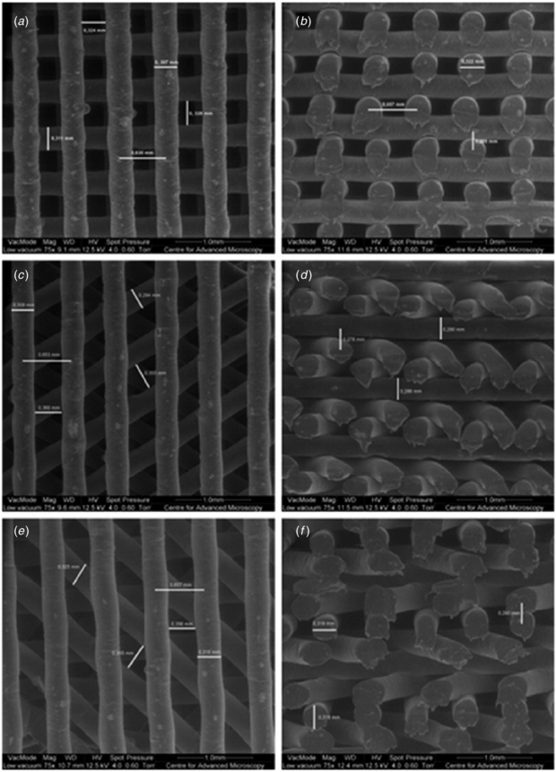
Figure 5. SEM micrographs of PCL scaffolds characterized by different lay-down patterns. (a) Top view, 0°/90° lay-down pattern, (b) cross section view, 0°/90° lay-down pattern, (c) top view, 0°/60°/120° lay-down pattern. (d) cross section view, 0°/60°/120° lay-down pattern, (e) top view, 0°/45°/90°/135° lay-down pattern and (f) cross section view, 0°/45°/90°/135° lay-down pattern.
Download figure:
Standard image High-resolution imageBy increasing the number of deposition angles from 2 (0°/90°) to 4 (0°/45°/90°/135°) it was possible to generate more complex pore geometries without a significant variation of the structure's porosity, as illustrated in table 3.
Table 3. Morphological characteristics of rapid prototyped structures for different lay-down patterns, at a fixed FD of 650 µm.
| Lay-down pattern | RW (µm) | FG (µm) | LG (µm) | Porosity (%) |
|---|---|---|---|---|
| 0°/90° | 313 ± 8 | 333 ± 12 | 249 ± 14 | 55 |
| 0°/60°/120° | 298 ± 10 | 350 ± 13 | 509 ± 13 | 55 |
| 0°/45°/90°/135° | 318 ± 1 | 358 ± 8 | 874 ± 7 | 54 |
Independently of the pore size or geometry, all the scaffolds produced were characterized by a fully open pore structure and good adhesion between adjacent layers.
Typical stress–strain curves obtained for the 3D rapid prototyped scaffolds are reported in figure 6, which graphically highlight the effect of FD and lay-down pattern on the mechanical performances of the constructs.
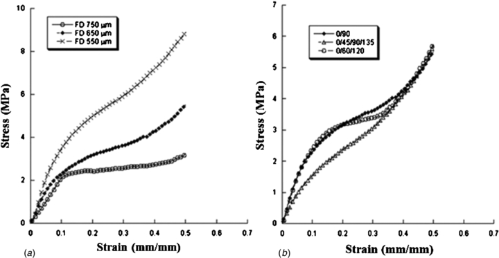
Figure 6. Effect of FD and lay/down pattern on the mechanical behaviour of 3D rapid prototyped scaffolds. Typical stress–strain curves obtained for scaffolds characterized by (a) 0°/90° lay-down pattern and different FDs (550, 650 and 750 µm), (b) FD of 650 µm and different lay-down patterns (0°/90°, 0°/60°/120° and 0°/45°/90°/135°).
Download figure:
Standard image High-resolution imageThe mechanical behaviour of the 3D rapid prototyped scaffolds results is similar to that of a flexible foam [73, 74]. A linear region is initially well evident, thus suggesting a stiff mechanical response at the onset. This region is then followed by a region with lower stiffness. Finally another stiff region of the stress–strain curve can be observed that resembles the densification region usually reported for flexible foams [73].
As already shown by previous works [41, 63, 74], unlike the typical behaviour of flexible foams [73] and 3D scaffolds manufactured through fused deposition modelling [75], the central region of the stress–strain curve does not evidence a plateau, which means a zero slope region, it is just characterized by a lower stiffness when compared with the other two regions of the graph.
The compressive modulus (E) has been calculated as the slope of the initial linear region of the stress–strain curve. Values of compressive modulus and maximum stress are reported as mean value ± standard deviation (tables 4 and 5).
Table 4. Effect of FD on the mechanical properties of 3D rapid prototyped scaffolds. Compressive modulus (E) and maximum stress (σmax) reported as mean value ± standard deviation, for scaffolds characterized by a 0°/90° lay-down pattern and different FDs (550, 650 and 750 µm). Statistical differences (p < 0.05) were observed in terms of compressive modulus and maximum stress.
| Filament distance FD (µm) | Compressive modulus E (MPa) | Maximum stress σmax (MPa) |
|---|---|---|
| 750 | 23.1 ± 2.8 | 2.7 ± 0.5 |
| 650 | 34.2 ± 3.8 | 5.6 ± 0.2 |
| 550 | 52.5 ± 4.5 | 8.7 ± 1.2 |
Table 5. Effect of lay-down pattern on the mechanical properties of 3D rapid prototyped scaffolds. Compressive modulus and maximum stress reported as mean value ± standard deviation, for scaffolds characterized by a FD of 650 µm and different lay-down patterns (0°/90°, 0°/60°/120° and 0°/45°/90°/135°). Statistical differences (p < 0.05) were observed in terms of the compressive modulus between 3D scaffolds with a 0°/45°/90°/135° lay-down pattern and other architectures.
| Lay-down pattern | Compressive modulus E (MPa) | Maximum stress σmax (MPa) |
|---|---|---|
| 0°/90° | 34.2 ± 3.8 | 5.6 ± 0.2 |
| 0°/60°/120° | 30.5 ± 4.5 | 5.0 ± 0.6 |
| 0°/45°/90°/135° | 19.1 ± 2.8 | 4.9 ± 0.3 |
As expected, at fixed lay-down pattern and processing parameters, the FD strongly affects the porosity and consequently the mechanical behaviour of 3D rapid prototyped structures. In particular, as the FD increases from 550 to 750 µm (porosity increases from 49% to 57%), the compressive modulus and maximum stress decrease from 52.5 ± 4.5 MPa to 23.1 ± 2.8 MPa and from 8.7 ± 1.2 MPa to 2.7 ± 0.5 MPa, respectively (table 4). In terms of the compressive modulus and maximum stress, the observed differences are statistically significant. Our results are in agreement with previous works performed by other researchers and confirm the porosity dependence of 3D scaffolds when tested under compression [61, 73, 76]. A plausible explanation for the variation in mechanical properties as a function of FD, independently of the material, can be attributed to the column-like behaviour of the filament junctions when undergoing compression. In other words, for a specific area, the scaffold with a smaller distance between filaments has a maximum number of columns, hence increasing the stiffness of the scaffold [76].
On the other hand, at selected FD and processing parameters, the lay-down pattern influences the mechanical behaviour of the scaffolds. As reported in table 5, scaffolds characterized by a 0°/90° (2-angle) pattern exhibit a compressive modulus (34.2 ± 3.8 MPa) and maximum stress (5.6 ± 0.2 MPa) which are greater than those obtained for 0°/60°/120° (3-angle) and 0°/45°/90°/135° (4-angle) patterns. In this case, a decrease in the amplitude of the deposition angle (from 0°/90° to 0°/45°/90°/135°) between struts of adjacent layers implied a larger contact area (fused area), leading to a decrease of the local stress experienced by the 3D structure [60]. Thus, when the scaffolds are compressed, the filaments deposited with a smaller lay-down pattern (0°/45°/90°/135°) can easily slide from each other increasing the scaffold deformability [75]. Anyway, only the differences in terms of the compressive modulus are statistically significant between 3D scaffolds with a 0°/45°/90°/135° lay-down pattern and the other architectures analysed in the work.
In the case of weight-bearing applications such as bone, 3D scaffolds are required to withstand mechanical stresses, both in vitro as in vivo, during a specific period of time, providing adequate pore size and interconnectivity for cell adhesion/proliferation, vascularization and tissue ingrowth. Besides, a scaffold that fails to match the mechanical properties of the native tissue may cause tissue resorption and anomalous growth (if the scaffold has higher mechanical properties than those of the natural tissue) or the complete failure of the scaffold (due to insufficient strength to withstand physiological loads) [19]. As reported by Yang , the values of the compressive strength and the young modulus of human cancellous bone are 4–12 MPa and 0.02–0.5 GPa respectively, which suggests that PCL scaffolds produced via BioCell Printing may also have a great potential in bone TE applications [21].
Finally, as suggested by some authors, the mechanical properties of some synthetic polymers may vary greatly when tested under wet conditions (water, PBS, etc) and over a range of temperatures [75, 77, 78]. From our analysis, no relevant change in the mechanical properties was observed when 3D PCL scaffolds pre-conditioned in PBS for 48 h were tested under compression at 37 °C (data not shown). A plausible explanation for these results lies in the fact that the PCL is highly hydrophobic and crystalline, which presents greater resistance to the plasticizing effect caused by PBS or water. Further support to this observation was provided through studies previously conducted by our group, where we found that PCL scaffolds conditioned in PBS or SBF for six months, kept their physical and structural integrity almost intact [79].
3.1.2. Cell adhesion/proliferation assay
The ultimate goal of a TE scaffold is to closely mimic the native tissue environment, providing adequate chemical, physical and biological cues that will guide cell adhesion, proliferation and differentiation. According to the cell type, scaffold requirements, such as pore size, shape and porosity, may change; therefore, the scaffold should be tailored in order to better accommodate the growth of specific cells [19]. Moreover, the cell colonization of 3D porous matrices is strongly dependent on the ability of cells to bridge pores and spread into the scaffold. If the pores are too large or too small, cells will fail to spread and form networks throughout the scaffold. Therefore, it becomes important to define an optimal pore size range for supporting cell ingrowth [65].
Biological experiments were carried out on PCL scaffolds using hMSCs, to provide insight into the effect of pore size and shape on cell viability, morphology and migration. Cells were seeded at an appropriate density (17 × 103 cells re-suspended in 200 µl) directly onto the PCL scaffolds, regardless of pore size and shape, and allowed to proliferate for 21 days under static conditions. At pre-determined intervals of 7, 14 and 21 days the scaffolds/cells were withdrawn from the incubator and a quantitative evaluation of cell viability was performed by means of Alamar Blue™ assay. The results showed a strong influence of pore size and geometry on cell viability (figure 7).

Figure 7. Alamar Blue™ cell viability assay performed on PCL scaffolds with (a) different pore sizes and (b) with different pore geometries.
Download figure:
Standard image High-resolution imageIn general, 3D matrices should be characterized by an internal architecture with sufficiently large and fully interconnected pores to enable cell migration, transport of oxygen and nutrients, metabolic waste removal and vascularization, which are essential requirements in terms of cell vitality. The particular mechanism that promotes or blocks cell attachment, proliferation and differentiation of cells in scaffolds with different pore sizes and shape is not yet fully understood. Quantitative biological data depicted in figure 7(a) reveal that, independently of the pore size, all constructs were able to maintain a high level of cell viability during the incubation period (21 days). Nonetheless, substantial differences in terms of Alamar Blue™ reduction verified at day 21 suggest that scaffolds with larger FDs (FD = 750 µm and pore size of 450 µm) are able to accommodate a higher number of viable cells when compared to scaffolds with smaller FDs (FD = 550 µm and pore size of 250 µm). These differences in terms of cell viability may be related with the larger surface area available (higher porosity) for cells to adhere and proliferate inside the scaffolds with a larger pore size. Furthermore, cell activity appears to be enhanced by the more effective transport of nutrients and oxygen that occurs within scaffolds with larger internal channels.
Regarding the influence of pore shape on cell viability, results depicted in figure 7(b) clearly show an increment on cell viability with the decreasing number of deposition angles. Despite this, a difference can be detected throughout the entire incubation period, which becomes more evident after 21 days of cell culture.
Based on SEM images (figure 5), all specimens exhibited a fully open internal pore architecture, independently of the deposition angle, that in itself should promote an equal cell colonization of the structures. Therefore, the differences found in terms of cell viability according to pore shape can be explained by the angle amplitudes between the filaments that geometrically define the pores in the XY plane of the fabrication process. Our observations reveal that by passing from a complex polygonal shape with 45° amplitude between filaments to quadrangular pore geometry with 90° amplitude, the distance between filaments in the same plane is increased thus improving cell accessibility and consequent colonization of the inner part of the scaffolds. Similar work performed by Hoque reports no significant differences on the proliferation of rSMC cells seeded onto PCL and PCL–PEG scaffolds with different pore shapes, after three weeks in culture [80]. The authors attributed this fact to the complete open pore structure of all three patterns that favoured the nutrient flow in and wastes flow out. This apparently contradictory result needs to be interpreted with caution as the findings of the authors were based on experiments performed with different cells (rSMC) and 3D scaffolds designed/produced applying a higher FD that resulted in different pore geometries from those presented in our study.
During the adhesion process, large pores will induce cells to attach only to a single strut hence feeling the stimuli of the surface, while in small pores, cells can attach to several struts, thus resulting in multiple stimuli. Looking at the scaffolds with smaller pore size (FD = 550 µm) it is possible to observe that the struts in the same plane are much closer, thus creating multiple contact points for the cell to attach to and to eventually differentiate. Additionally, scaffolds with larger pores also possess a higher porosity providing cells with more open space to adhere and proliferate.
Parallel investigations of cell morphology were carried out by confocal laser scanning microscopy (CLSM) in order to highlight the effect of pore size and shape on the adhesion and proliferation of cells on the filaments of the scaffolds (figure 8). Based on our observations, it was not possible to detect significant differences in cell morphology between the different pore topologies. Taking into account that both surface material chemistry and topography affect cell adhesion and proliferation, the similar cell morphology may be ascribed to the fact that the fabrication technology and the material employed to manufacture all the structures were the same.
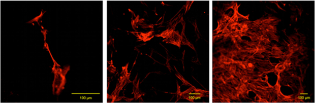
Figure 8. Typical results from confocal analyses performed on cell-scaffold constructs at 7 (a), 14 (b) and 21 (c) days after cell seeding that evidence the phalloidin-labelled actin filaments of hMSCs adhered to PCL fibres of the scaffold.
Download figure:
Standard image High-resolution imageThe CLSM images allowed us to confirm the quantitative results obtained with Alamar BlueTM. As it becomes clear from figure 8, the number of viable cells adhering and proliferating onto the filaments of the scaffolds strongly increases from day 7 to day 21. Cell morphology also varied along the incubation period changing from a circular geometry with a few ramifications (figure 8(a)) to a homogeneous filamentary geometry with an increased number of ramifications (figure 8(c)). This variation indicates an increment in terms of cell adhesion through the establishment of a higher number of cell-scaffolds and cell–cell interactions.
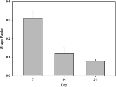
Additional studies of cell adhesion and spreading were performed based on CLSM images with the aim of determining the shape factor of the cells. The shape factor was calculated for all pore topologies based on equation (4). Since no relevant variations were observed between the different pore topologies, we decided to report only the values of the shape factor for scaffolds with quadrangular pores (0°/90°) and FD = 750 µm. Typical values of the shape factor at 7, 14 and 21 days after cell seeding time are reported in figure 9 as mean value ± standard deviation.
Figure 9. Typical values of shape factor obtained from CLSM images of hMSC deposited on scaffolds with quadrangular pores (0°/90°) and FD = 750 µm. Results were obtained at day 7, 14 and 21 and are reported as mean value ± standard deviation.
Download figure:
Standard image High-resolution image
As it shows in figure 9, the mean cell shape factor decreased significantly from 0.31 ± 0.04 at day 7 to 0.08 ± 0.01 at day 21. Based on previous experiments performed by other authors, it is possible conclude that the lower the cell shape factor, the more elongated the cells [64]. In other words, the establishment of multiple cellular extensions (increased total cellular area) implies a reduction in the shape factor (elongated cells) leading to better adhesion and spreading process.
The output of this study reveals a strong influence of pore size and shape on the adhesion, viability/proliferation of hMSCs seeded and cultured on PCL scaffolds over 21 days. Our findings suggest that large quadrangular pores enhance in vitro hMSC proliferation. As such, we envisage the combination of large quadrangular pores with small triangular pores within a single scaffold as a possible solution towards the design of a functional graded structure capable of promoting optimal tissue regeneration. We believe that such structures should have small pores on the outside (where the access to oxygen and nutrients is much easier) and large pores inside (enabling access to oxygen and nutrient supply) thus forcing cells to migrate to the inner part of the scaffolds and promoting a homogeneous colonization.
Besides these findings, it becomes clear that the information available in the literature regarding the optimal pore size and shape for the adhesion and proliferation of specific cell lines, both in vitro and in vivo, remains very inconsistent and sometimes even contradictory. Therefore, we believe that BioCell Printing holds great potential in this matter, increasing the level of structural accuracy and reproducibility in the fabrication of scaffolds, expanding the range of materials possible of being processed and reducing the process variability inherent to other fabrication methods (e.g. conventional techniques).
4. Conclusions
A systematic approach to the analysis of 3D PCL scaffolds manufactured through BioCell Printing was performed. A detailed study was carried out in order to evaluate the effect of these morphological characteristics on the biomechanical response of the 3D structures. The 3D rapid prototyped scaffolds had pore sizes and porosity ranges of 245–433 µm and 49–57% respectively, as the FD was varied between 550 and 750 µm and the lay-down pattern was fixed at 0°/90°. On the other hand, by adopting three different lay-down patterns of 0°/90°, 0°/60°/120° and 0°/45°/90°/135° and maintaining a constant FD of 650 µm, it was possible to obtain scaffolds with quadrangular, triangular and complex internal geometries, respectively. Compressive mechanical tests showed that by increasing pore size (porosity) or the number of deposition angles, there is a weakening of the structures.
After 21 days of static culture, hMSC viability/proliferation appeared to be strongly influenced by the pore size and shape of the scaffolds. From quantitative and qualitative analysis it was possible to draw certain conclusions of particular interest: (1) large quadrangular pores enhance hMSC viability and proliferation; (2) cell morphology does not seem to be affected by pore topology, as demonstrated by the assessment of the shape factor.
Furthermore, this research may be considered as a first step of a future work that should extend our investigations to other scaffold materials and architectures, cell lines and culture conditions (in vitro dynamic culture or in vivo), providing important insights into the field of soft and hard tissue engineering.
Acknowledgments
This work was performed with the partial financial support provided by the Fundação para a Ciência e Tecnologia through the strategic project Pest-OE/EME/UI4044/2011. Authors wish to thank Professor Geoffrey Mitchell and his team at CFAM for their support in recording SEM images of scaffolds.